Step 5 Press the phone firmly into the wall bracket and slide the phone down. The tabs in the bracket click into
position.
Step 6 Proceed to Adjust the Handset Rest, on page 46.
Remove the Phone from the Non-Lockable Wall Mount
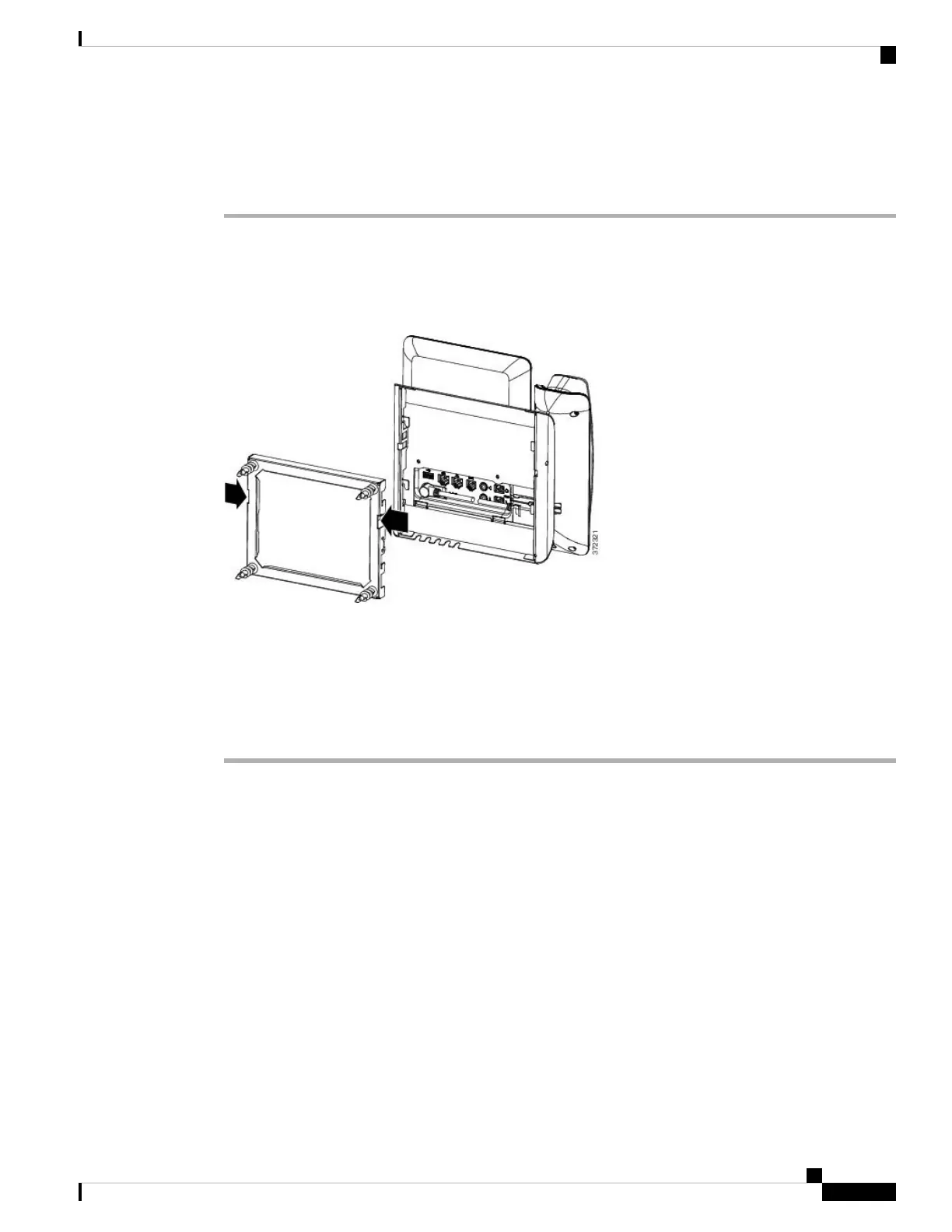
The wall bracket has two tabs that lock the kit together. Use the following illustration to locate the tabs.
Figure 13: Tab Location
Before you begin
Obtain two Phillips head screwdrivers or other similar devices that have a diameter of 5 millimeters or 3/16ths
of an inch.
Procedure
Step 1 Insert a screw driver or other device into the left and right holes in the phone mounting plate. Insert to a depth
of about 3/4 of an inch or 2 centimeters.
Step 2 Press firmly inwards to disengage the tabs.
Cisco IP Phone Accessories
39
Cisco IP Phone Accessories
Remove the Phone from the Non-Lockable Wall Mount

 Loading...