SignalPinSignalPinSignalPinSignalPin
VccTx29GND19LPMode_Reset9
Vcc130GND20VccRx10
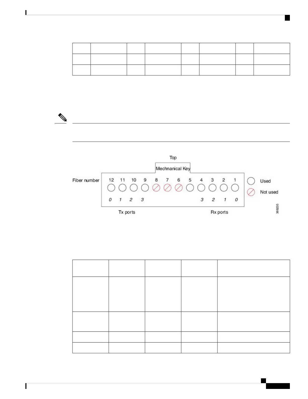
MPO-12 Connector Pin Specifications
The following figure shows the pinouts and corresponding fiber numbers for the CPAK multifiber push-on
(MPO-12) male connector.
In the following figure, the male MPO connector alignment pins are on the CPAK side so the cable MPO
connectors will be female.
Note
Figure 86: MPO-12 100-Gigabit Connector Pinouts
Looking into the receptacle of the CPAK module with the mechanical key on top, the fibers are numbered 12
through 1 (left to right). Fibers 12, 11, 10, and 9 are used for the optical Tx signals. Fibers 4, 3, 2, and 1 are
used for the optical Rx signals.
CPAK Connector Types
Connector TypesModeDistanceSpeedCPAK Product
Number
MPO-24 to MPO-24 (100G)
MPO-24 to LC breakout (10x10G)
MPO-24 to MPO-12 breakout
(2X40G)
Multi-mode100m100G
10x10G SR
2x40G SR4
CPAK-100G-SR10
MPO-12Multi-mode70m (OM3)
100m (OM4)
100GCPAK-100G-SR4
SCSingle-mode10m100GCPAK-100G-LR4
MPO-24 to LC breakoutSingle-mode10m10GCPAK-10x10G-LR
Cisco ASR 9000 Series Aggregation Services Router Ethernet Line Card Installation Guide
151
Technical Specifications
MPO-12 Connector Pin Specifications