17
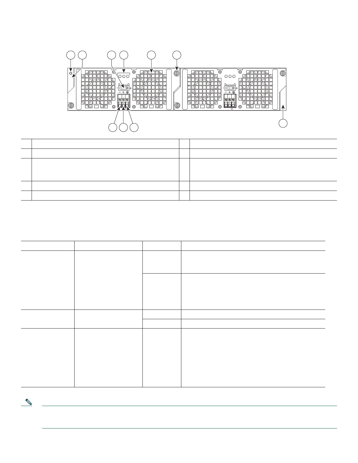
Figure 13 –48V DC Power Supply for the Cisco ASR 1002-X Router
Table 2 describes the –48V DC power supply LEDs on the Cisco ASR 1002-X Router.
Table 2 Cisco ASR 1002-X Router –48V DC Power Supply LEDs
Note The color coding of the DC-input power supply leads depends on the color coding of the DC power source at your site.
Typically, green or green/yellow is used for ground. Make certain the lead color coding you choose for the DC-input
power supply matches lead color coding used at the DC power source.
1
Chassis ESD socket
6
–48V DC power supply captive installation screw
2
–48V DC power supply slot 0 label
7
–48V DC power supply slot 1 label
3
–48V DC power supply switch Standby/On (I) (standby
symbol is a broken circle with a vertical line through the
top of it)
8
Negative ground lead
4
–48V Dopier supply LEDs
9
Positive ground lead
5
Fan
10
Earth ground lead
LED Label LED Color Description
INPUT OK A bi-color LED indicates
presence of input voltage
Green Signals that the DC power supply input voltage is greater
than –43.5VDC at turn-on and remains green down to
–39VDC.
Amber The power supply turns off due to low input voltage
(falls below –39VDC) and indicates that there is still a
voltage present (voltage on the terminal block). The LED
remains amber and is active to around 20V +/-5V. The
LED is not illuminated if the input is below 15V.
FAN OK A bi-color LED indicates
power supply fan status
Green All fans are operational.
Red A fan failure is detected.
OUTPUT FAIL Power supply activity Red It is off signals that the DC output voltage are within the
normal operating range. Output voltage between the
minimum and maximum limits will not create an output
fail alarm, and output voltages below the minimum or
above the maximum will create an Output Fail alarm.
When you turn the power supply on, the red LED
illuminates for two to three seconds to test LED
operation before going off.
280289
OUTPUT INPUT
FAIL
OK OK
FAN
-48V/-60V 16A
This unit might have more than
one power supply connection.
All connections must be removed
to de-energize the unit.
OUTPUT INPUT
FAIL
OK OK
FAN
-48V/-60V 16A
This unit might have more than
one power supply connection.
All connections must be removed
to de-energize the unit.
9 810
4 5 63
0
1
7
1
2

 Loading...


