7
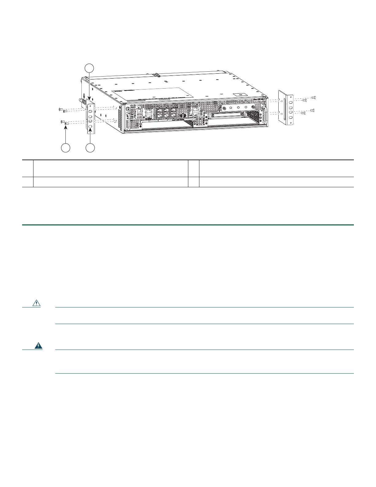
Figure 3 Attaching the Cable-Management Brackets to the Cisco ASR 1002-X Router
Step 4 Using a Phillips screwdriver and cable-management screw, thread and tighten the screw to the cable-management
bracket.
Step 5 Repeat Step 1 through Step 4 for the other side of the Cisco ASR 1002-X Router.
This completes the procedure for installing the cable-management brackets on a Cisco ASR 1002-X Router for a chassis
rack-mount configuration.
Chassis Ground Connection Installation
Connecting the Cisco ASR 1002-X chassis to earth ground is required for all DC-powered installations and AC-powered
installations where compliance with Telcordia grounding requirements is necessary.
Caution The dual-lug chassis ground stud must be installed, and all the cards and filler plates must be fully inserted and
screwed in and earthed to prevent a potential hazard in a telecom line.
Have the recommended tools and supplies available before you begin this procedure.
Warning
This equipment must be grounded. Never defeat the ground conductor or operate the equipment in the absence of
a suitably installed ground conductor. Contact the appropriate electrical inspection authority or an electrician if
you are uncertain that suitable grounding is available.
Statement 1024
Before you connect the power or turn on the power to your router, you must provide an adequate chassis ground (earth)
connection for the Cisco ASR 1002-X Router. The chassis ground lugs (two) and the respective screws (four) are provided in
the accessory kit that is shipped with your Cisco ASR 1002-X Router.
The following tools, equipment, and supplies are necessary to connect the system ground to the chassis:
• Phillips screwdriver
• Dual-lug chassis ground component (two) and respective screws (four)
• Grounding wire
See Figure 4 for the location of the chassis ground connector on the Cisco ASR 1002-X Router.
1
Secure the cable-management bottom screw and top screw
to this ear hole
3
Front rack-mount bracket
2
Cable-management U type device
 Loading...


