9
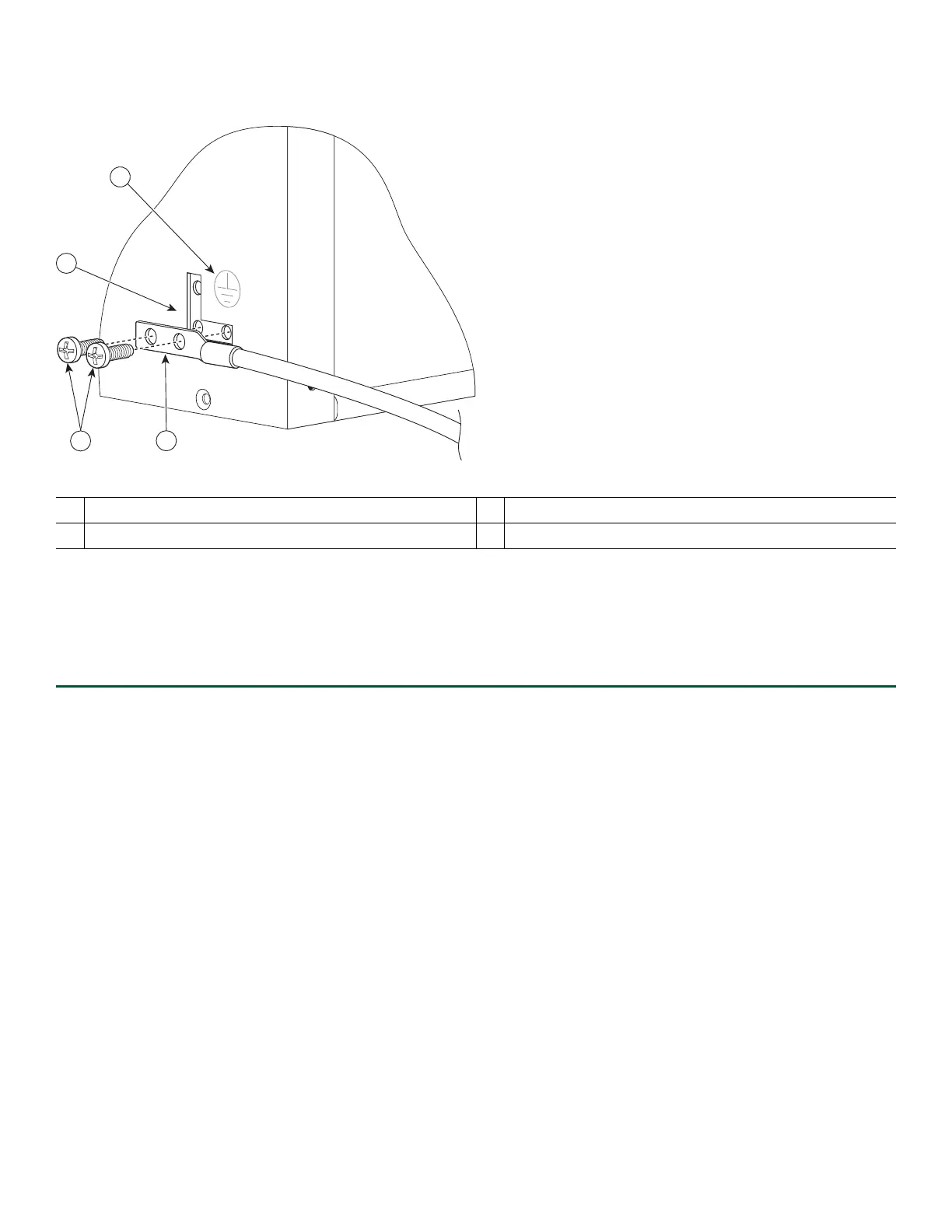
Figure 6 Attaching a Grounding Lug to the Chassis Ground Connector
Step 6 Insert the two screws through the holes in the grounding lug.
Step 7 Use the Number 2 Phillips screwdriver to carefully tighten the screws until the grounding lug is held firmly to the
chassis. Do not overtighten the screws.
Step 8 Connect the opposite ends of the grounding wire to the appropriate grounding point at your site to ensure an adequate
chassis ground.
This completes the procedure for attaching a chassis ground connection. Go to the procedure described in the “Connect the
Router to the Network” section on page 9 for information about connecting the router to the network.
4 Connect the Router to the Network
This section provides information about cables and ports and attaching the router to the network.
• Console and Auxiliary Port Cable Connections, page 9
• Connect the Ethernet Management Port, page 10
• Connect the Shared Port Adapter Cables, page 11
• Install the Cables Using the Cable-Management Brackets, page 11
Console and Auxiliary Port Cable Connections
This section describes how to attach a cable to the console port or auxiliary port on the Cisco ASR 1002-X Router. The Cisco
ASR 1002-X Router has two RJ-45 ports for terminal connection. A console port, which can be utilized for terminal connections
and an auxiliary port for additional terminal connections as well as diagnostic utilization.
1
Chassis earth ground studs and lead wire
3
Earth ground connector on the chassis
2
Ground screws
4
Earth ground symbol

 Loading...


