EasyManuals Logo

Cisco ASR 1002-X User Manual

Cisco ASR 1002-X
48 pages
To Next Page IconTo Next Page
To Previous Page IconTo Previous Page
Page #8 background imageLoading...
Page #8 background image
8
Figure 4 Cisco ASR 1002-X Router Ground Connector Location
Perform the following steps to install chassis ground connection:
Step 1 Use the wire stripper to strip one end of the AWG #6 wire approximately 0.75 inches (19.05 mm).
Step 2 Insert the AWG #6 wire into the wire receptacle in the grounding lug.
Step 3 Use the manufacturer’s recommended crimping tool to carefully crimp the wire receptacle around the wire. This step is
required to ensure a proper mechanical connection.
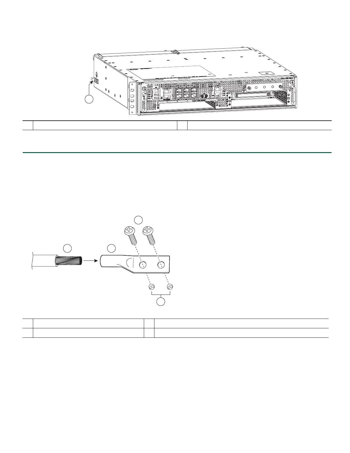
Figure 5 shows how to attach a ground lug to the chassis ground connector.
Figure 5 Attaching a Grounding Lug to the Chassis Ground Connector
Step 4 Attach the grounding lug with the wire on the left to avoid having the grounding wire overlapping the power supply.
Step 5 Locate the chassis ground connector on the side of your chassis.
1
Cisco ASR 1002-X Router ground stud location.
1
Chassis ground connector holes
3
Ground screws
2
Grounding stud
4
Chassis ground lead wire
333427
1
50536
1
2
3
4

Other manuals for Cisco ASR 1002-X

Questions and Answers:

Question and Answer IconNeed help?

Do you have a question about the Cisco ASR 1002-X and is the answer not in the manual?

Cisco ASR 1002-X Specifications

General IconGeneral
Form FactorRack-mountable
Rack Units2RU
Integrated ServicesYes
Maximum Memory16 GB
Built-in Gigabit Ethernet Ports6
Input Voltage100-240 VAC
Operating Temperature32 to 104°F (0 to 40°C)
RedundancyPower supply redundancy
Network Interface ModulesUp to 4 SPA/SIP slots
Embedded Services Processor (ESP)ESP-20
Maximum Packet per Second (PPS)15 Mpps
Height3.5 inches
Fixed Ports6 GE ports
Memory4 GB (default), 16 GB (maximum)
Power SupplyDual power supplies (AC or DC)
Dimensions (H x W x D)3.5 x 17.5 x 19.0 in (8.9 x 44.5 x 48.3 cm)

Related product manuals