24
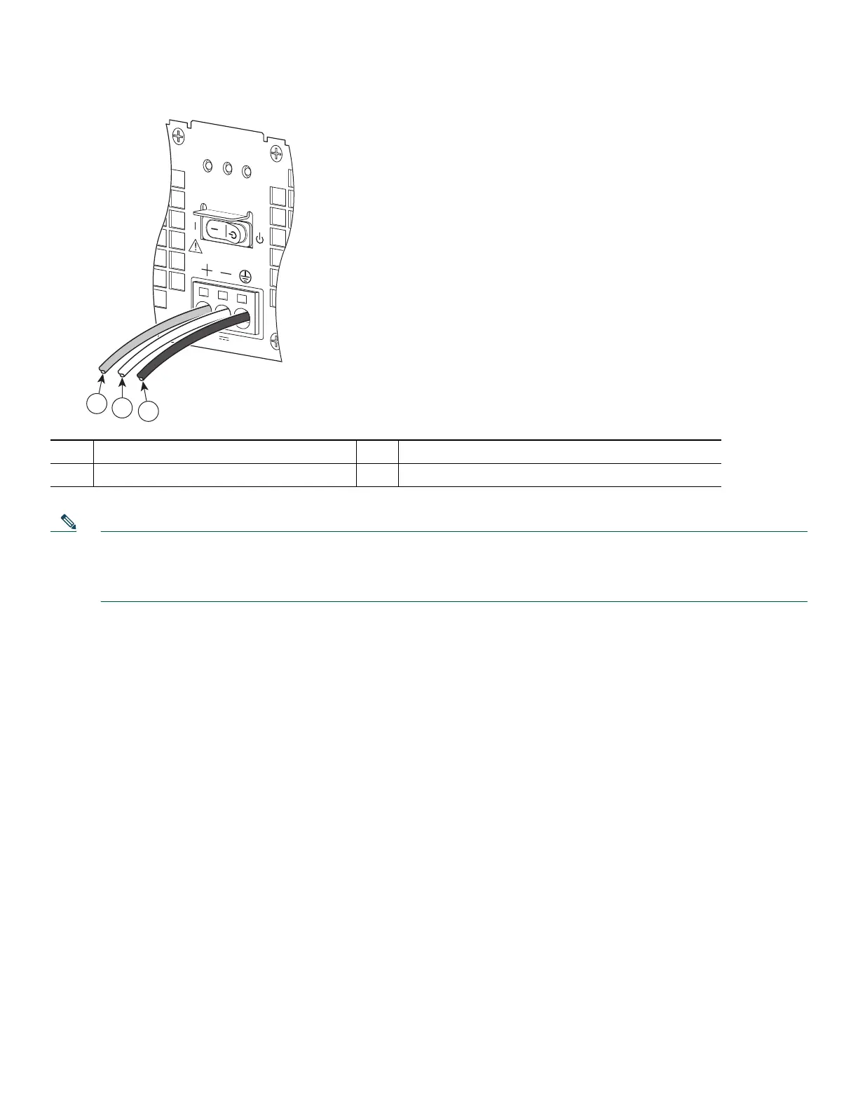
Figure 22 Cisco ASR 1002-X Router +24V DC Power Supply Lead Wires Installed
Note The color coding of the DC-input power supply leads depends on the color coding of the DC power source at your site.
Typically, green or green/yellow is used for ground (GND), black is used for –48V on negative (–) terminal and red is
used for RTN on the positive (+) terminal. Make certain the lead color coding you choose for the DC-input power
supply matches lead color coding used at the DC power source.
Step 10 After inserting the ground wire leave an extra service loop in the ground lead to ensure that the ground lead is the last
lead to disconnect from the power supply if a great deal of strain is placed on all three leads. Use a cable tie wrap to
secure the three leads to the power supply faceplate. There are tabs on the power supply to use for the tie wraps as
shown in Figure 23.
1 Positive lead wire (usually red) 3 Ground (GND) lead wire (green/yellow)
2 Negative lead wire (black)
OUTPUT INPUT
FAIL
OK OK
FAN
This unit might have more than
one power supply connection.
All connections must be removed
to de-energize the unit.
+27V DC INPUT
+27V 32A
253170
3
2
1

 Loading...


