23
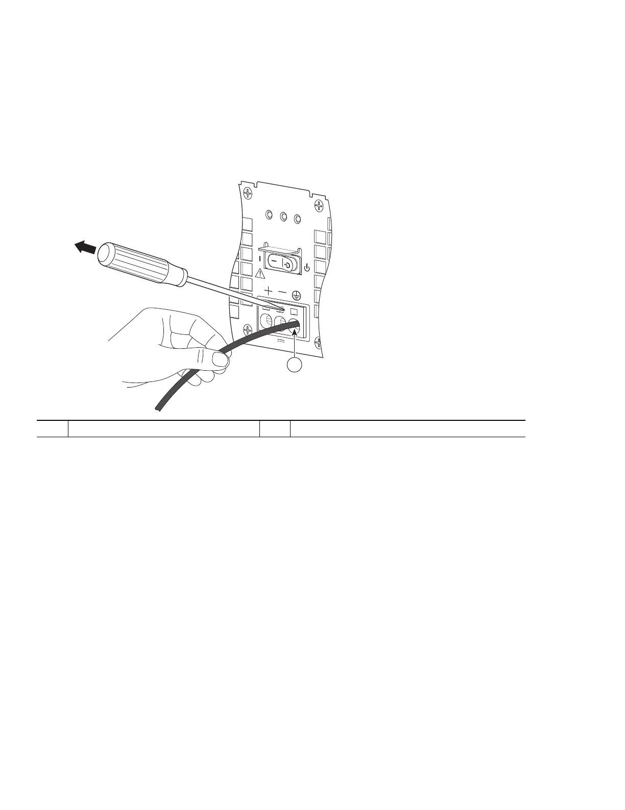
Step 7 After the lead wire is fully inserted, hold the lead wire in place by pressing inward while you remove the screwdriver to
release the spring to tension down on the installed lead wire.
Step 8 Once the screwdriver is completely removed, gently pull on the lead wire to make certain that the lead wire is securely
installed.
Figure 21 shows a lead wire fully inserted and the screwdriver removed while you gently pull on the lead to make certain it is
secured in the terminal block.
Figure 21 Removing the Screwdriver from the Cisco ASR 1002-X Router +24V DC Power Supply
Step 9 Repeat Steps 5 through Step 8 for each lead wire. Figure 22 shows the leads wires installed in the terminal block.
1
+24V DC lead ground wire
OUTPUT INPUT
F
A
I
L
OK
O
K
F
AN
T
his
unit
m
ight hav
e
more than
o
ne pow
er s
upply c
on
n
e
c
tion.
All connections m
ust
be
r
em
ov
ed
to de-energize the
unit.
+27V DC INPUT
+2
7V
32A
1
253169

 Loading...


