10
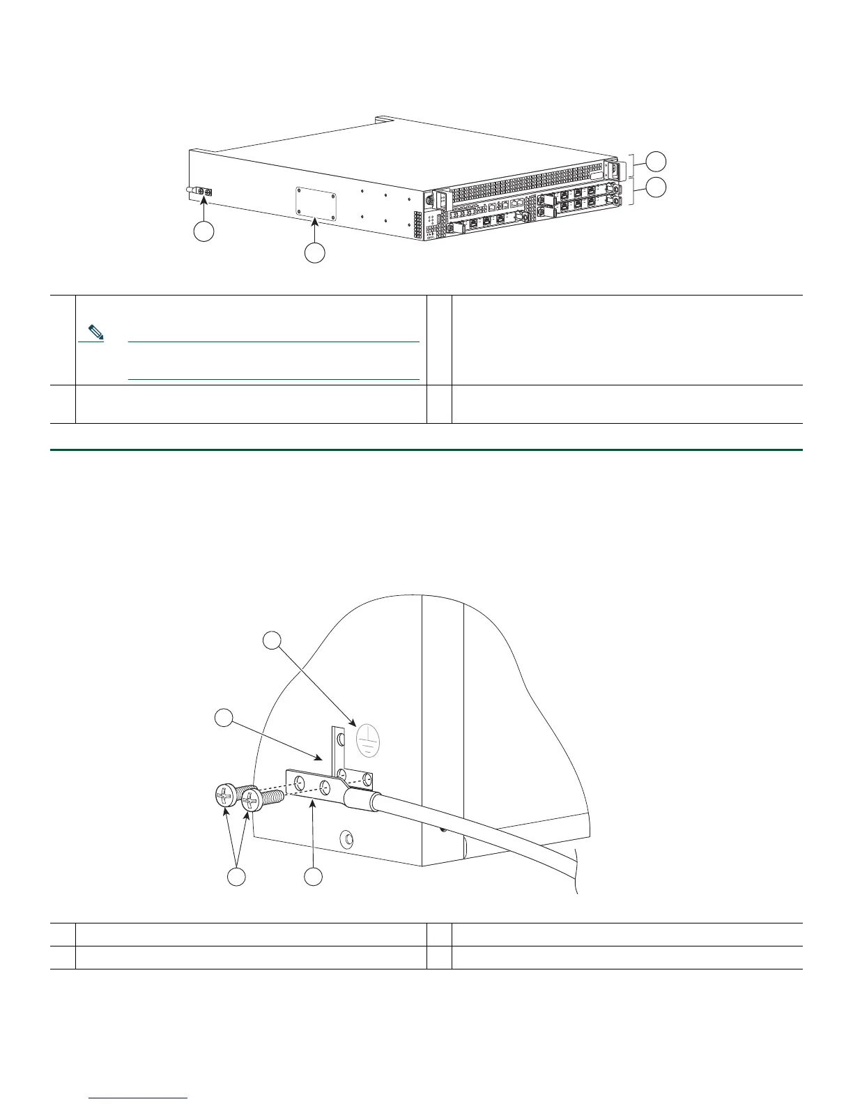
Figure 6 Cisco ASR 1002 Router Ground Connector Location and eUSB Panel Door
Step 1 Use the wire stripper to strip one end of the AWG #6 wire approximately 0.75 inches (19.05 mm).
Step 2 Insert the AWG #6 wire into the wire receptacle on the grounding lug.
Step 3 Use the manufacturer’s recommended crimping tool to carefully crimp the wire receptacle around the wire; this step is
required to ensure a proper mechanical connection.
Figure 7 Attaching a Ground Lug to the Chassis Ground Connector
Step 4 Attach the grounding lug with the wire on the left to avoid having the grounding wire overlapping the power supply.
1
F0 with Cisco ASR1000-ESP5 or Cisco ASR1000-ESP10
Note The Cisco ASR10002 Router does not support
the Cisco ASR1000-ESP20 module.
3
The eUSB panel door on the side of the Cisco ASR 1002
Router must not be opened. If there is a problem with
eUSB flash card, the chassis should be returned.
2
R0 slot with embedded ASR1000-RP1 and embedded
ASR1000-SIP10
4
Cisco ASR 1002 Router ground stud location
1
Chassis ground lug
3
Chassis ground connector location
2
Ground lug screws
4
Earth ground symbol
AS
R
1
002
s
t
a
t
p
w
r
m
in
m
aj
c
r
it
S
P
A
-
4XOC
3-P
O
S
S
T
A
T
U
S
0
1
2
3
C
/A
A
/
L
C
/A
A
/
L
C
/A
A
/
L
C
/A
A
/
L
S
P
A
-
4XOC
3-P
O
S
S
TA
TU
S
0
1
2
3
C
/A
A
/
L
C
/A
A
/L
C
/
A
A
/
L
C
/A
A
/
L
S
TA
T
QE
0
Q
E
1
Q
E
2
QE
3
B
O
O
T
C
A
R
R
I
E
R
L
I
N
K
P
W
R
S
T
ATMT
S
M
G
MT
A
U
X
C
O
N
S
PA
-4
X
O
C
3
-POS
S
T
A
T
U
S
0
1
2
3
C
/
A
A
/L
C
/A
A
/
L
C
/A
A
/
L
C
/
A
A
/L
3
1
2
4
280283
280034
3
4
2
1

 Loading...


