34
Step 7 Replace the DC power supply within five minutes or the system will shutdown.
You have completed the procedure for removing a DC power supply from the Cisco ASR 1002 Router.
Installing the DC Power Supply
This section provides information about replacing a DC power supply in the Cisco ASR 1002 Router.
Note The color coding of the DC-input power supply leads depends on the color coding of the DC power source at your site.
Typically, green or green/yellow is used for ground. Make certain the lead color coding you choose for the DC-input
power supply matches lead color coding used at the DC power source.
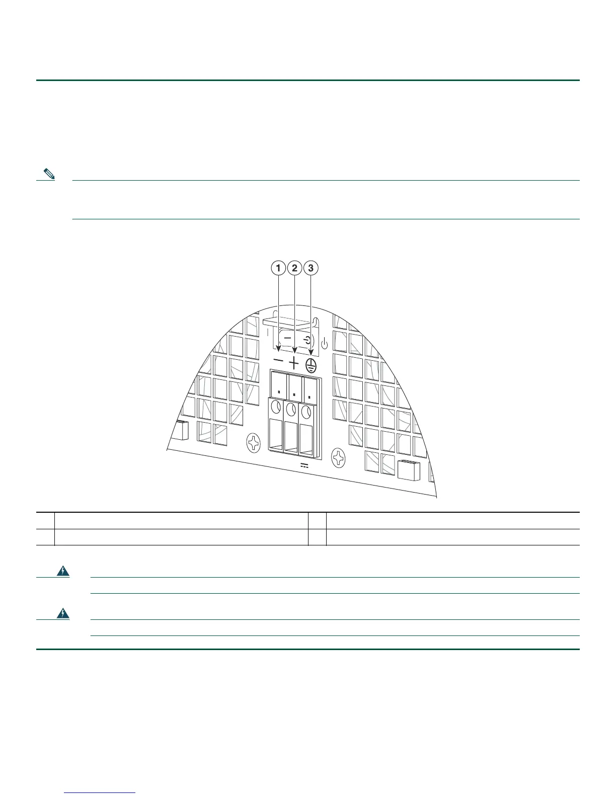
Figure 17 Cisco ASR 1002 Router Terminal Block
Warning
Never install an AC power module and a DC power module in the same chassis.
Statement 1050
Warning
Installation of the equipment must comply with local and national electrical codes.
Statement 1074
Step 1 At the rear of the router, check that the power supply Standby switch is in the Standby position.
Step 2 Ensure that the negative and positive leads are disconnected from the site power source and the circuit breaker is turned
off.
Step 3 Insert a DC power supply in power supply slot 0 or power supply slot 1 until it is full seated.
Step 4 Using a wire stripper, strip approximately 0.55 inch (14 mm) from the negative, positive, and ground lead.
1
Negative lead
3
Earth ground symbol
2
Positive lead
280291

 Loading...


