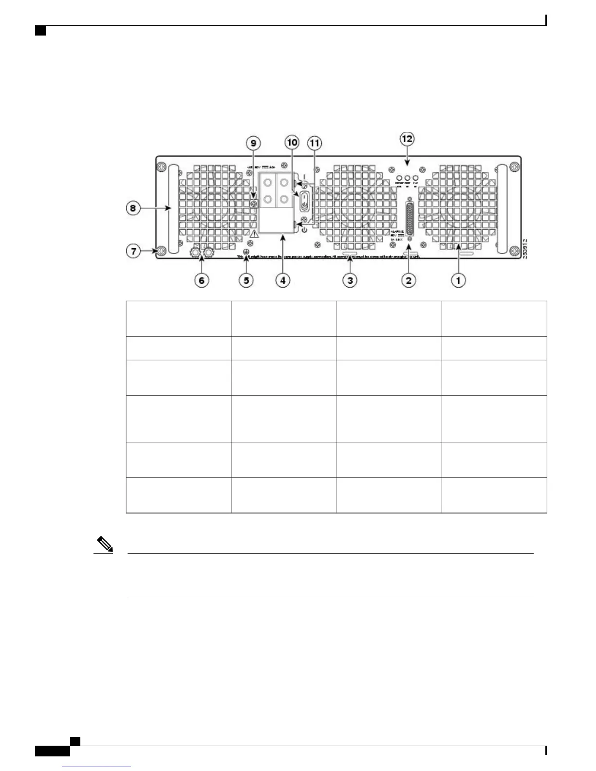
The following image shows the ASR1013/06-PWR-DC power supply of the Cisco ASR 1006 Router.
Figure 16: Cisco ASR 1006 Router
–
48 VDC Power Supply (ASR1013/06-PWR-DC)
DC power supply captive
screw
7Fan1
DC power supply handle8DB-25 alarm connector2
Terminal block and
plastic cover single screw
9Tie-wrap tab3
On/Off (|/O) circuit
breaker switch
10DC power supply
terminal block and plastic
cover
4
Terminal block and
plastic cover slot tab
11Ground symbol5
Power supply LEDs12DC power supply ground
studs
6
Shielded cables must be used to connect to the DB-25 alarm connector on both the AC and DC power
supplies in order to comply with the FCC/EN55022/CISPR22 Class A emissions requirements. See the
“How Cisco ASR1000-RP Alarm Monitoring Works” section on page 2-22 .
Note
Before you begin the procedure to connect DC input power, read these important notices:
•
The color coding of the DC input power supply leads depends on the color coding of the DC power
source at your site. Typically, green or green/yellow is used for ground (GND), black is used for –48 V
on negative (–) terminal, and red is used for RTN on the positive (+) terminal. Make certain the lead
color coding you choose for the DC input power supply matches the lead color coding used at the DC
power source.
Cisco ASR 1000 Series Router Hardware Installation Guide
32
Cisco ASR 1006 Router Overview and Installation
Connecting DC Input Power to Cisco ASR 1006 Router
 Loading...


