AUXiliary port2CONsole port1
Step 2
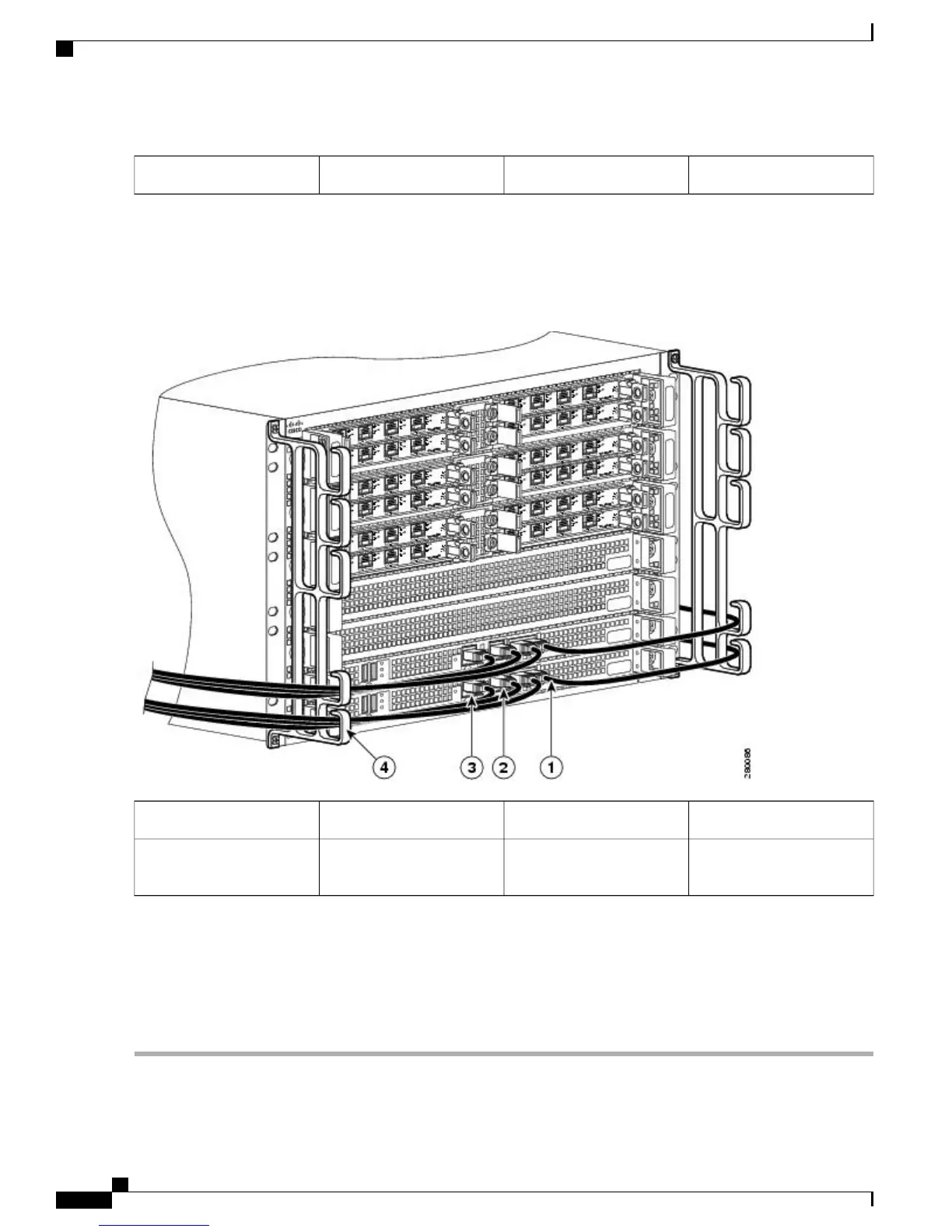
Run the cable up and through the cable-management bracket and connect the other end of the RJ-45 cable to the RJ-45
adapter (see the following image).
Figure 23: Cable-Management Bracket with Cabling in the Cisco ASR 1006 Router
BITS port3AUXiliary connection1
Cable-management U
feature device
4MGMT Ethernet port2
Step 3
Connect the adapter to your video terminal to complete the cable connection.
Step 4
Power on your video terminal.
Step 5
Configure your video terminal to match the following default console port settings: 9600 baud, 8 data bits, No parity
generation or checking, 1 stop bit, and No flow control.
Step 6
Go to the Connecting the System Cables, on page 41 to continue the installation.
Cisco ASR 1000 Series Router Hardware Installation Guide
40
Cisco ASR 1006 Router Overview and Installation
Connecting a Terminal to the Cisco ASR 1000 Series RP Console Port
 Loading...


