2-65
Cisco ASR 9000 Series Aggregation Services Router Overview and Reference Guide
OL-17501-09
Chapter 2 Functional Description
Power System Functional Description
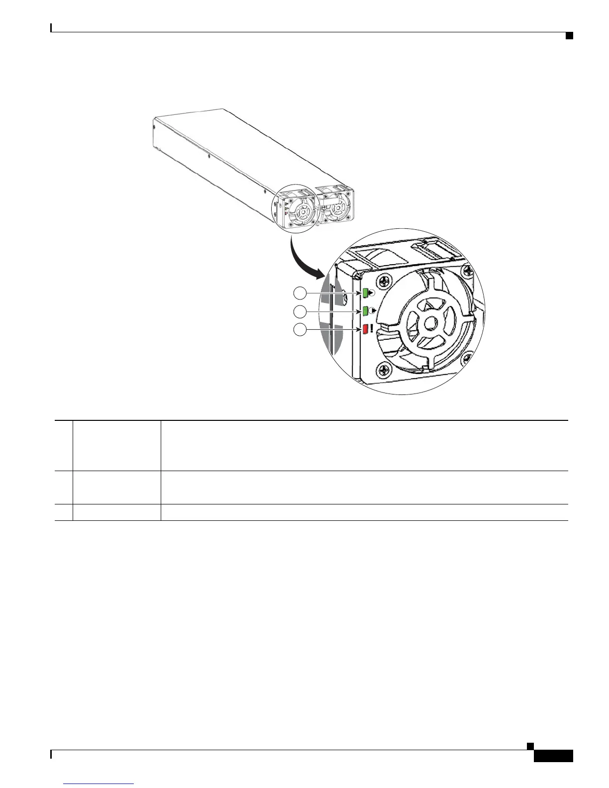
Figure 2-56 Version 2 Power Module Status Indicators
System Power Redundancy
Both the AC and DC power systems have system power redundancy depending on the chassis
configuration. Each tray can house up to four modules and can be configured for multiple power
configurations. For more information about power system redundancy, see the “Power Supply
Redundancy” section on page 3-3.
1 Input LED ON continuously when the input voltage is present and within the correct range.
BLINKING when the input voltage is out of acceptable range.
OFF when no input voltage is present.
2 Output LED ON when the power module output voltage is present.
BLINKING when the power module is in a power limit or overcurrent condition.
3 Fault LED ON to indicate that a power supply failure has occurred.
284405
1
2
3

 Loading...


