Step 6
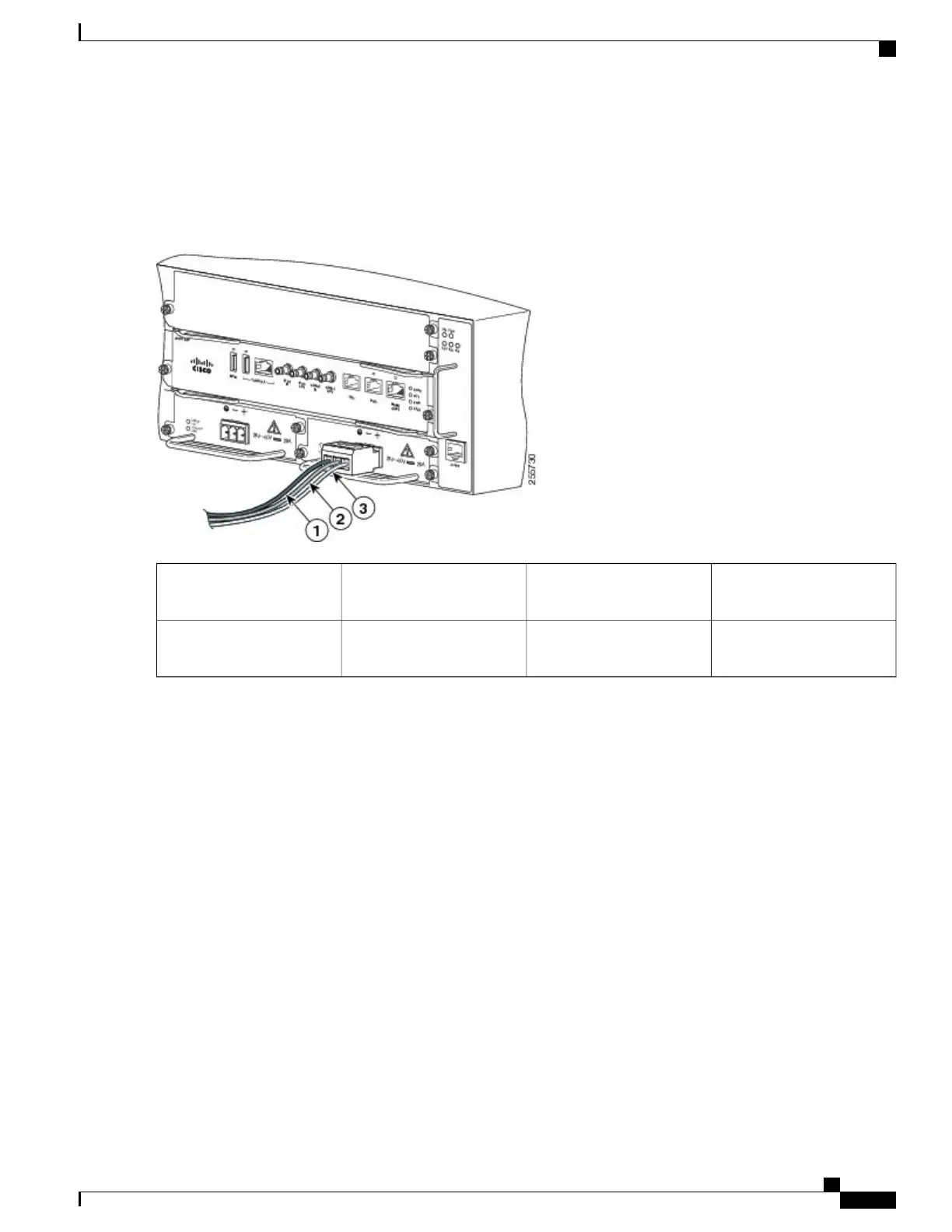
Repeat Step 4 through Step 5 for the remaining DC input power source wire and the ground wire. The figure below
shows the wiring completed for a terminal block plug.
Figure 65: Inserting the DC Power Supply Terminal Block Plug in the Block Header
DC power supply positive
(+) lead wire
3DC power supply ground
lead wire
1
——
DC power supply negative
(-) lead wire
2
Secure the wires coming in from the terminal block plug so that they cannot be disturbed by casual contact.Caution
Cisco ASR 903 Aggregation Services Router Hardware Installation Guide
107
Installing the Cisco ASR 903 Router
Installing the DC Power Supply

 Loading...


