EasyManuals Logo

Cisco Catalyst 2960-X Series User Manual

Cisco Catalyst 2960-X Series
102 pages
To Next Page IconTo Next Page
To Previous Page IconTo Previous Page
Page #49 background imageLoading...
Page #49 background image
Attaching the RPS Connector Cover
This section only applies to the switches that have an RPS port.
If an RPS is not connected to the switch, install an RPS connector cover on the back of the switch. Statement
265
Warning
Before You Begin
The Catalyst 2960X-24PSQ-L switches do not have an RPS connector and a cover is not needed.Note
Procedure
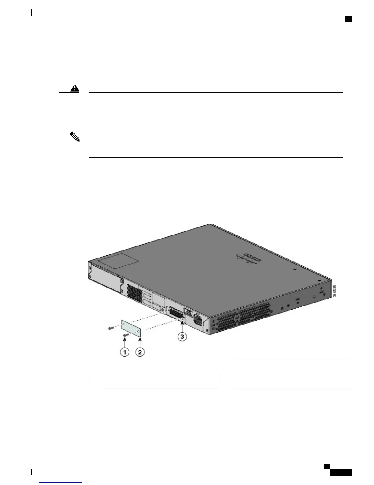
If you are not using an RPS with your switch, use the two Phillips pan-head screws to attach the RPS connector
cover to the back of the switch.
Figure 20: Attaching the RPS Connector Cover
RPS connector3Phillips pan-head screws (48-0482-01)1
RPS connector cover2
Catalyst 2960-X and 2960-XR Switch Hardware Installation Guide
OL-28309-02 39
Switch Installation
Wall-Mounting

Table of Contents

Questions and Answers:

Question and Answer IconNeed help?

Do you have a question about the Cisco Catalyst 2960-X Series and is the answer not in the manual?

Cisco Catalyst 2960-X Series Specifications

General IconGeneral
Operating SystemCisco IOS
Form FactorRack-mountable
RAM512 MB
Model2960-X Series
Ports48 x Gigabit Ethernet
Uplink InterfacesOptional 1G or 10G uplinks
Switching CapacityUp to 160 Gbps
StackingYes, up to 8 switches
Power over EthernetPoE+ (IEEE 802.3at) available on selected models
Dimensions4.4 x 45 x 28.2 cm (1.73 x 17.7 x 11.1 in)
Weight5.4 kg
VLANs4096
Jumbo Frame Support9198 bytes
Power Supply100-240VAC, 50-60 Hz
FeaturesLayer 2 and Layer 3 features, QoS, IPv6 support
SoftwareLAN Base
Operating Temperature0 to 45°C (32 to 113°F)

Related product manuals