Installing a CAT 6/6A Ethernet Cable and Gland Assembly to the Access Point
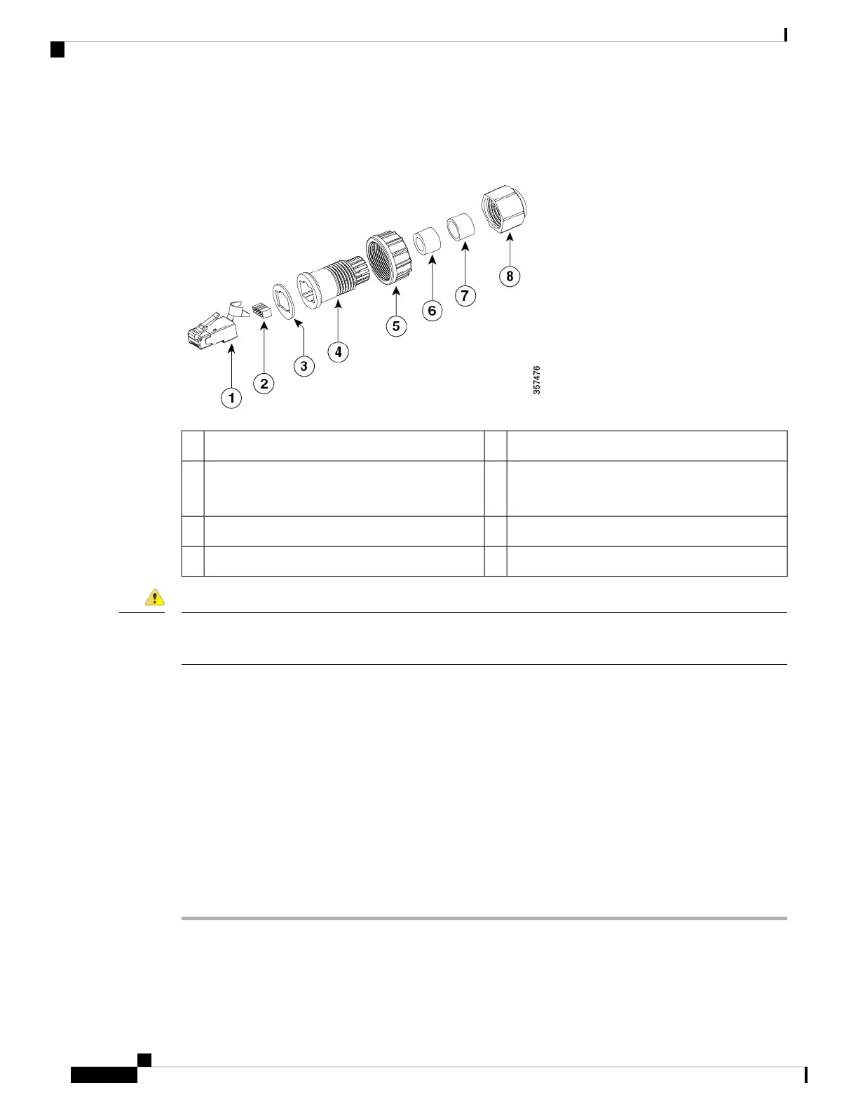
Figure 81: CAT 6/6a Cable Gland Assembly
Screw nut5CAT 6/6A RJ45 Plug1
Cable Seal (Cable OD range 5 mm to 7 mm)6RJ45 wire load bar
Note the orientation into plug
2
Cable Seal (Cable OD range 7 mm to9 mm)7Gasket3
Cable sealing nut8Clamp ring4
This unit might have more than one power supply connection. All connections must be removed to
de-energize the unit. Statement 1028
Danger
Before you begin
You must supply these tools and materials:
• Shielded outdoor-rated Ethernet (CAT 6 or CAT 6A) cable with a diameter of 0.2 to 0.35 inch (5 to 9
mm)
• CAT 6 RJ-45 connector installation tool
• Adjustable wrench or 28–mm box wrench
• CAT 6 / CAT 6A gland ordered separately with AIR-ACC-CAT6= kit
Procedure
Step 1 Disconnect power to the power injector and ensure all power sources to the AP are turned off
Step 2 Ensure a 6 AWG ground wire is connected to the AP (see Grounding the Access Point, on page 66).
Step 3 Remove the covering cap from the PoE port.
Cisco Catalyst 9124AX Series Outdoor Access Point Hardware Installation Guide
74
Installation Overview
Installing a CAT 6/6A Ethernet Cable and Gland Assembly to the Access Point