DescriptionItem
SIM 13
Step 5 Push in each SIM until it clicks into place. When the SIMs are installed, re-attach the access plate previously
removed with a screwdriver. Torque to 2.8 to 3.8 inch-lbs (0.9-1.1 newton meter).
Ensure the cover is properly aligned with the screw hole.
Note
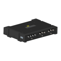
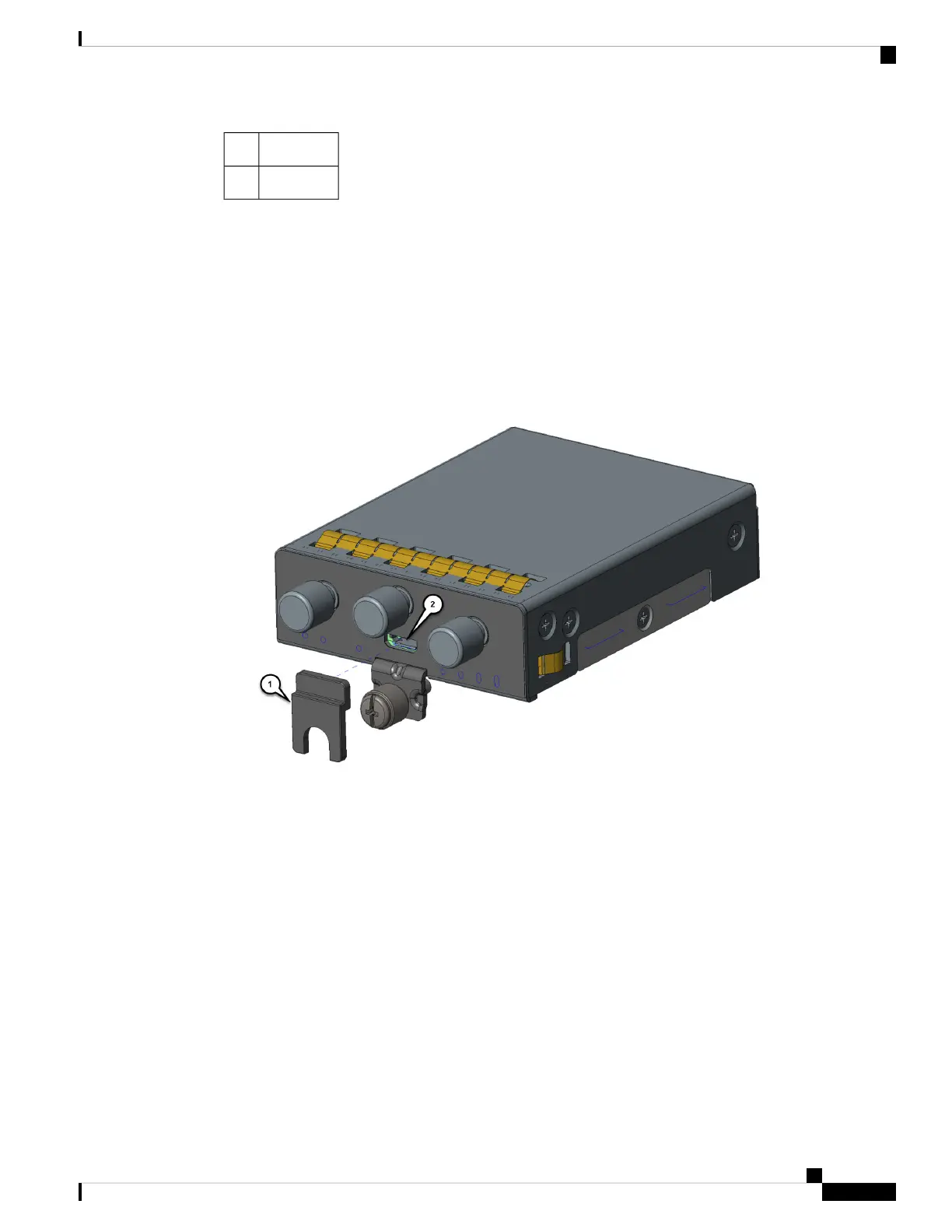
Step 6 If your Pluggable Module is the type that has a USB port, make sure that the USB cover is properly installed.
Place the USB cover (1) with the plug indentation against the USB port (2). The half circle of the USB cover
fits behind the latch lock screw. See the following graphic for details.
Figure 16: USB Port Cover Installation
Step 7 Tighten the latch lock screw to a torque of 2.8 to 3.8 inch-lbs (0.3 to 0.4 newton meter). Refer to the following
graphic for a finished USB cover installation.
Cisco Catalyst IR1800 Rugged Series Router Hardware Installation Guide
49
Pluggable Interface Modules
Installation
 Loading...