Table 2: Available PoE Power for CMICR-4PS and CMICR-4PC Switches
Available PoEPower Adapter Model
65 WPSU-80W-AC
50 W65 W AC to DC power adapter
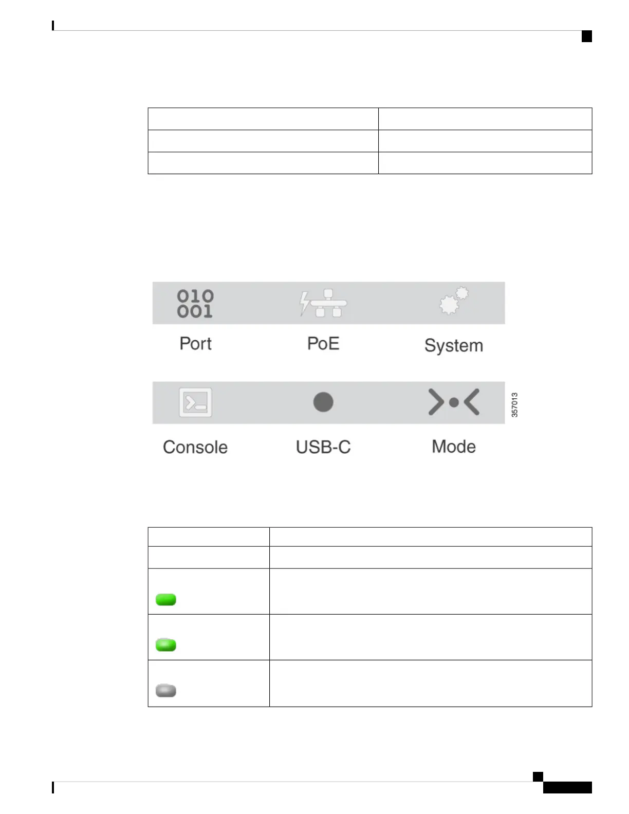
LEDs
You can use the system and port LEDs to monitor switch activity and performance. To conserve power, the
LEDs remain off by default when switch is powered on. Press the Mode button to turn on the LEDs.
Figure 4: Switch LEDs
Downlink Port Data LEDs
RJ-45 ports have port LEDs. These LEDs, as a group or individually, provide information about the switch
and about the individual ports.
DescriptionColor
No link or port was administratively shut down.Off
Link present but is not sending or receiving data.Green
Activity. Port is sending or receiving data.Blinking green
Link fault. Error frames can affect connectivity, and errors such as excessive
collisions, CRC errors, and alignment and jabber errors are monitored for link
faults.
Blinking green-amber
Cisco Catalyst Micro Series Switch Hardware Installation Guide
5
Product Overview
LEDs