53
Power Supply Installation
Power-Supply Module Installation
Warning: Only trained and qualified personnel should be allowed to install or replace this equipment.
Statement 1030
Warning: Hazardous voltage or energy may be present on power terminals. Always replace cover when terminals
are not in service. Be sure uninsulated conductors are not accessible when cover is in place. Statement 1086
1. Ensure that the power is off at the AC or DC circuits.
Locate the circuit breakers, turn them OFF, and tape them in the OFF position.
Warning: If the power is not off at the AC or DC circuit breaker, do not touch the power-input terminal.
Note: Do not connect the switch to a power source that has an ON/OFF switch.
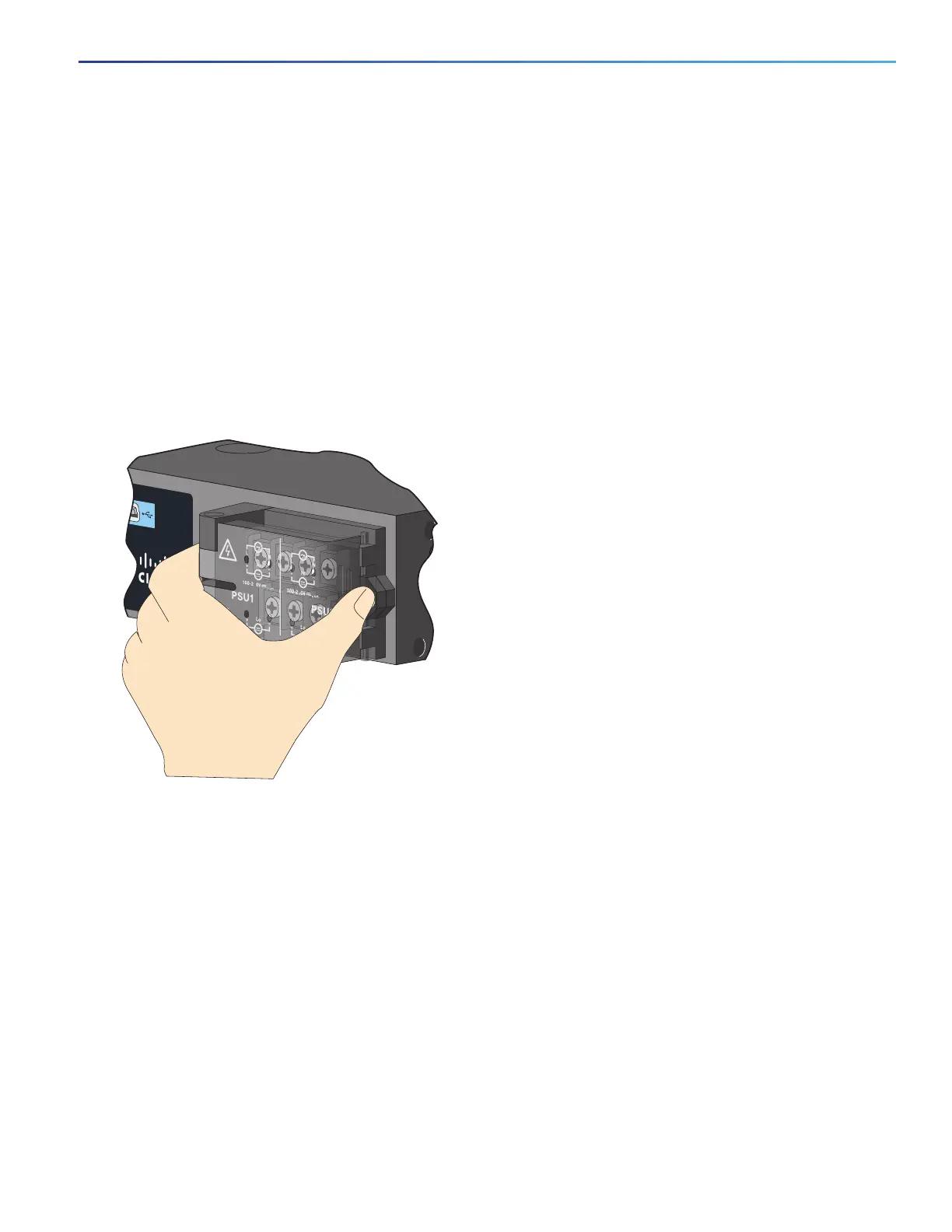
2. Use a Phillips screwdriver to loosen the captive screw on the power-input terminal, and open the cover.
Figure 44 Opening the Power-Input Terminal Cover
The terminal screws labels are on the power-input terminal cover. See Figure 45 on page 54.
Cisco CGS 2520
207426
100-240V~, 50-60Hz, 2A
100-240V~, 50-60Hz, 2A
5
2A
2A
10A
10A
5
 Loading...


