78
Connector and Cable Specifications
Cables and Adapters
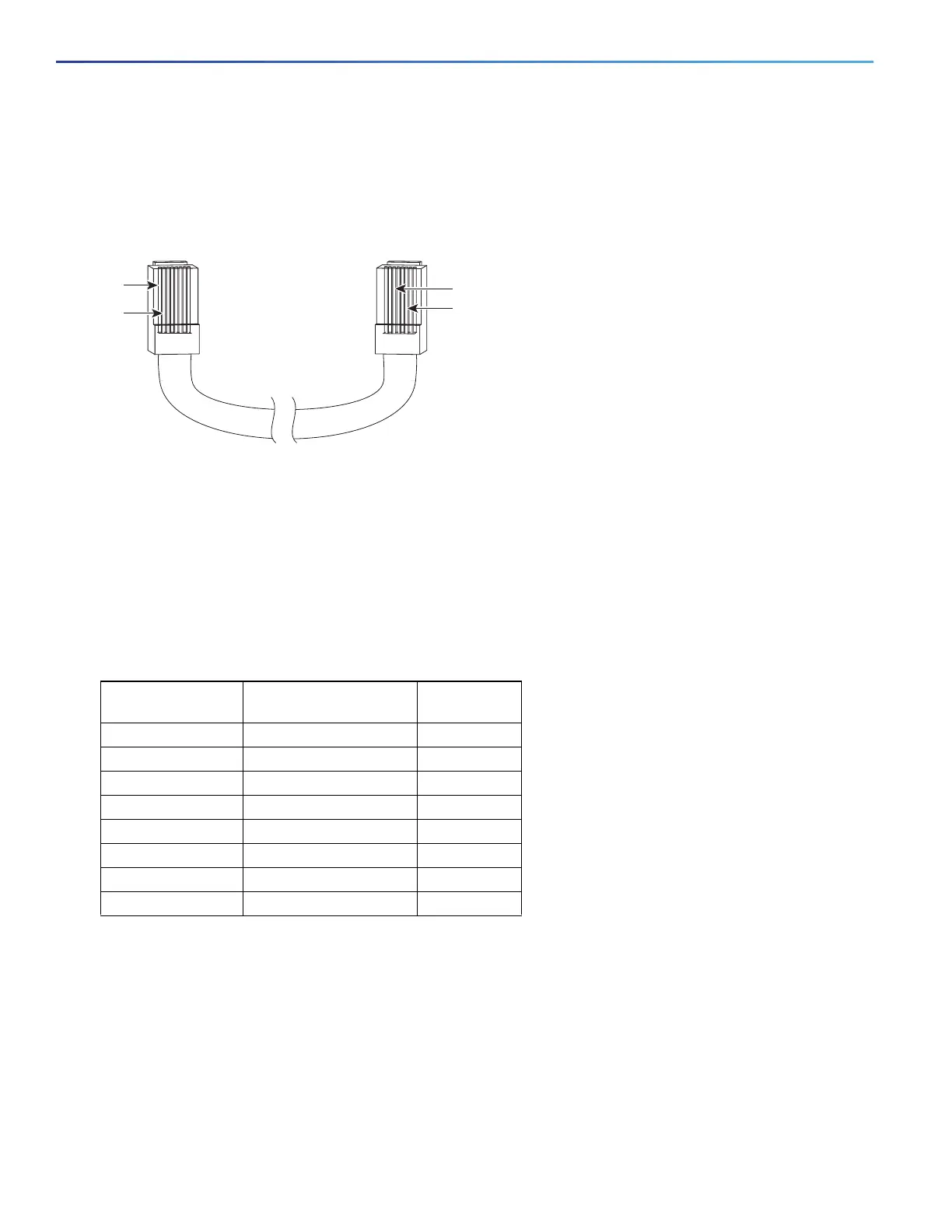
To identify a crossover cable, hold the cable ends side-by-side, with the tab at the back. The wire connected to pin 1
on the left end should be the same color as the wire connected to pin 3 on the right end. The wire connected to pin 2
on the left end should be the same color as the wire connected to pin 6 on the right end.
Figure 63 Identifying a Crossover Cable
Console Port Adapter Pinouts
The console port uses an 8-pin RJ-45 connector, which is described in Table 21 on page 78 and Table 22 on page 79.
If you did not order a console cable, you need to provide an RJ-45-to-DB-9 adapter cable to connect the switch console
port to a PC console port. You need to provide an RJ-45-to-DB-25 female DTE adapter if you want to connect the switch
console port to a terminal. You can order an adapter (part number ACS-DSBUASYN=). For console port and adapter
pinout information, see Table 21 on page 78 and Table 22 on page 79.
Table 21 on page 78 lists the pinouts for the console port, the RJ-45-to-DB-9 adapter cable, and the console device.
Table 22 on page 79 lists the pinouts for the switch console port, RJ-45-to-DB-25 female DTE adapter, and the console
device.
Note: The RJ-45-to-DB-25 female DTE adapter is not supplied with the switch. You can order this adapter from Cisco
(part number ACS-DSBUASYN=).
Pin 1
Pin 2
273807
Pin 6
Pin 3
Table 21 Console Port Signaling Using a DB-9 Adapter
Switch Console
Port (DTE)
RJ-45-to-DB-9
Terminal Adapter
Console
Device
Signal DB-9 Pin Signal
RTS 8 CTS
DTR 6 DSR
TxD 2 RxD
GND 5 GND
RxD 3 TxD
DSR 4 DTR
CTS 7 RTS
 Loading...


