Chapter 4 Connecting the Cisco RPS
Connecting Switches
4-10
Cisco Redundant Power System Hardware Installation Guide
OL-3654-01
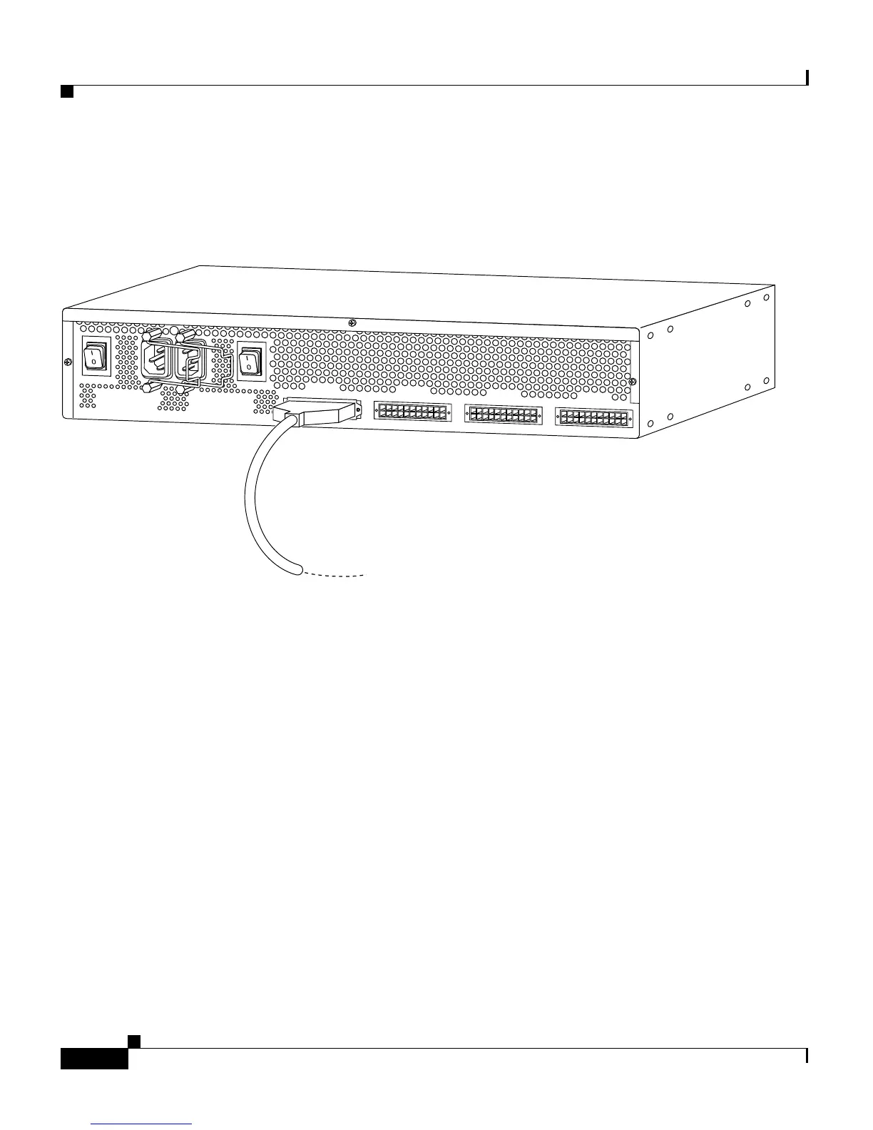
Step 3 Connect the other end of the one-to-one cable to the Cisco RPS rear-panel
connector, as shown in Figure 4-13.
Figure 4-13 Connecting the One-to-One Cable to the Cisco RPS
Step 4
On the Cisco RPS rear panel, connect an AC power cable to either or both of the
power connectors. Use the cable locks on the Cisco RPS to lock the cables in
place. (See Figure 4-14.)
29090
AC INPUT 1
100-200 V~ 50/60 Hz
10-5 A 1000 W
AC INPUT 2
100-200 V~ 50/60 Hz
10-5 A 1000 W
DC OUTPUT 1
DC OUTPUT 2
DC OUTPUT 3
DC OUTPUT 4