9-15
Cisco SCE8000 Installation and Configuration Guide, Rel 3.1.7
OL-16478-03
Chapter 9 Removal and Replacement Procedures
Removing and Replacing Modules
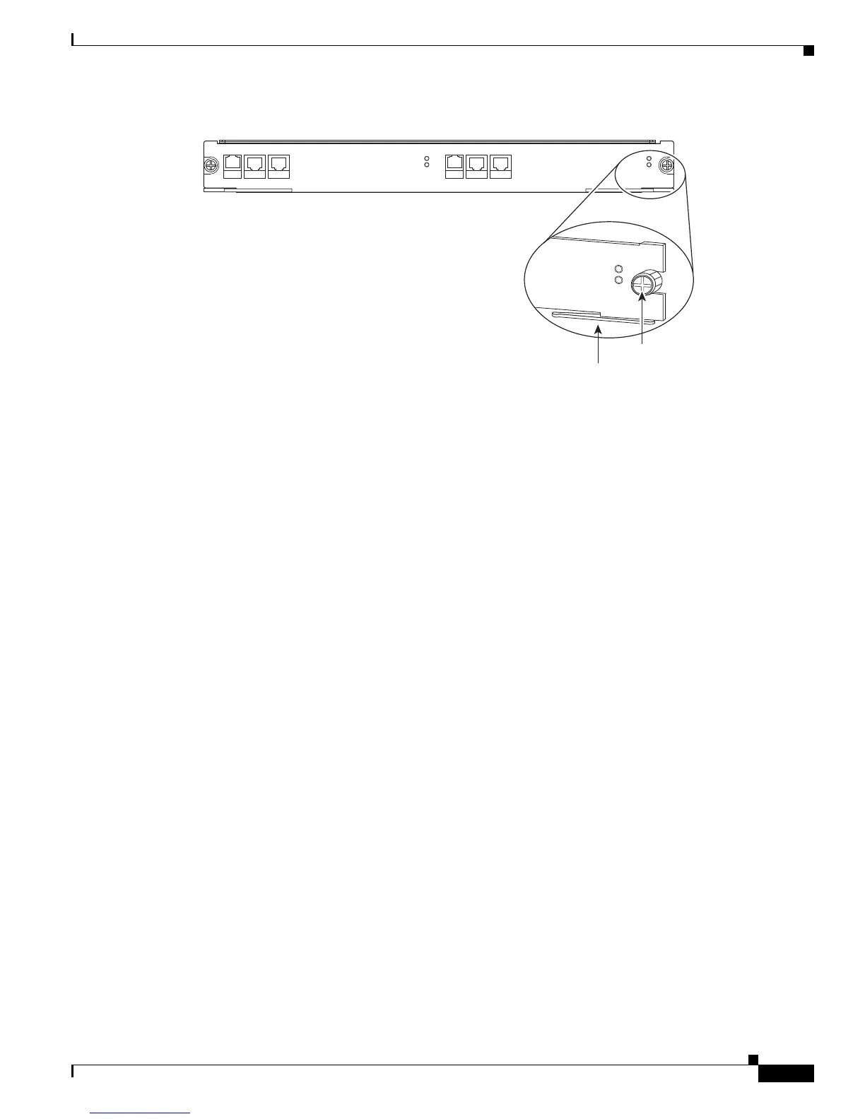
Figure 9-10 Ejector Levers and Captive Installation Screws
Step 7 Position the module in the slot. (See Figure 9-11.) Make sure that you align the sides of the module
carrier with the slot guides on each side of the slot.
SCE8000 EXTENDED SERVICE CONTROL MODULE
SCE8000-SCM-E
STATUS
OPTICAL BYPASS
MASTER
SYSTEM POWER
10/100/
1000
LINK/
ACTIVE
OPTICAL
BYPASS1
CONSOLE PORT1
10/100/
1000
LINK/
ACTIVE
OPTICAL
BYPASS2
AUX PORT2
270901
Ejector lever
SCE8000 EXTE
N
DE
D SE
RVICE CONTRO
L MODULE
MA
S
TE
R
SYS
TE
M
POWER
Captive
installation
screws

 Loading...


