9-16
Cisco SCE8000 Installation and Configuration Guide, Rel 3.1.7
OL-16478-03
Chapter 9 Removal and Replacement Procedures
Removing and Replacing Modules
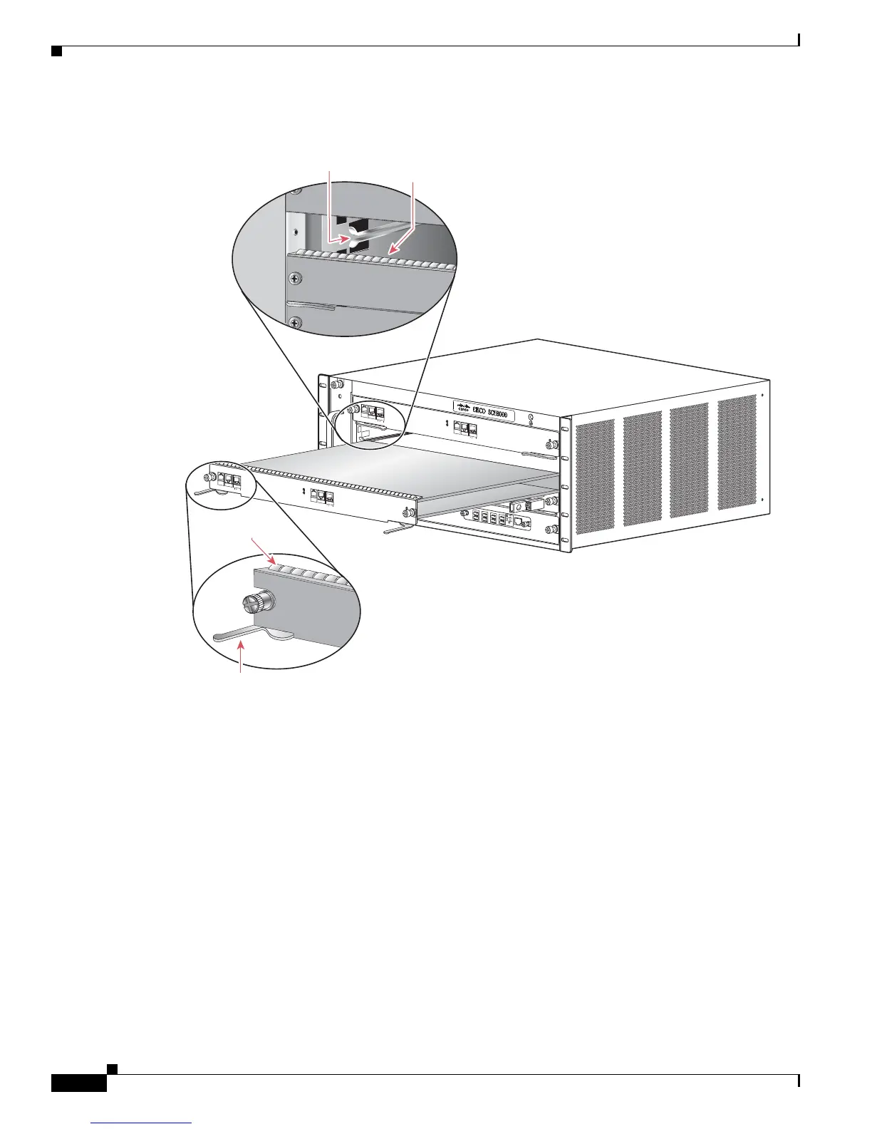
Figure 9-11 Positioning the Module in the Slot
Step 8
Carefully slide the module into the slot until the EMI gasket along the top edge of the module makes
contact with the module in the slot above it and both ejector levers have closed to approximately 45
degrees with respect to the module faceplate. (See Figure 9-12.)
F
AN
STATU
S
S
C
M
1
S
C
M
2
SI
P
3
4
SCE8000
-FA
N
S
Y
S
T
EM
P
OWE
R
OPTI
C
A
L
B
Y
PA
SS
ST
A
TU
S
A
U
X
PO
R
T2
L
I
N
K
A
C
TI
VE
M
A
S
TER
S
C
E
8
0
0
0
E
X
T
EN
D
E
D
SE
R
V
I
CE
C
O
N
T
R
O
L M
O
D
U
L
E
O
P
T
I
C
A
L
B
Y
P
A
S
S
O
P
T
I
C
A
L
BY
P
A
S
S
C
O
NS
O
L
E
10
100
100
0
LI
NK
A
CT
I
V
E
P
O
R
T1
A
C
A
B
C
D
B
D
S
TA
T
U
S
C
T
R
L
O
P
B
-
S
C
E
8
K-M
M
O
P
TI
C
A
L
BY
P
A
S
S
1
TX
R
X
T
X
R
X
T
X
R
X
TX
R
X
A
C
A
B
C D
B
D
STA
T
U
S
CTRL
O
PB-SCE8
K
-MM
OP
T
IC
A
L
B
Y
P
A
S
S
2
TX
R
X
TX
R
X
TX
R
X
TX
R
X
S
C
E
8
0
0
0-S
CM
-
E
S
CE
8
0
0
0-S
IP
S
TA
T
U
S
ACTIV
E/L
INK
SP
A
-1
X
10
G
E-
L
-V
2
S
T
A
TUS
A
C
T
I
V
E
/L
INK
SP
A-1
X
10
G
E-
L
-V
2
STA
T
U
S
ACTI
V
E/L
I
N
K
SP
A
-1X
1
0
G
E
-
L
-V
2
STA
T
U
S
ACTI
VE/
L
I
N
K
SP
A
-1X
1
0
G
E
-L
-V
2
1
0
1
0
0
1
0
0
0
S
YST
EM
P
OW
E
R
O
P
T
I
CA
L
B
Y
PAS
S
S
T
AT
U
S
A
U
X
P
O
R
T2
L
INK
A
CT
I
V
E
MA
S
T
E
R
S
C
E
8
0
0
0
E
X
T
E
ND
ED
SER
V
I
C
E
C
O
N
TRO
L
M
O
DU
L
E
O
P
TI
C
A
L
B
Y
P
A
S
S
O
P
T
ICAL
B
Y
P
A
S
S
C
ON
S
O
L
E
1
0
1
0
0
1
00
0
L
I
N
K
A
C
T
I
VE
P
O
R
T1
SCE8
0
0
0
-S
C
M
-
E
1
0
1
0
0
1
0
0
0
EMI gasket
Ejector lever fully
extended
270907
EMI gasket
Insert module
between slot guides

 Loading...


