9-17
Cisco SCE8000 Installation and Configuration Guide, Rel 3.1.7
OL-16478-03
Chapter 9 Removal and Replacement Procedures
Removing and Replacing Modules
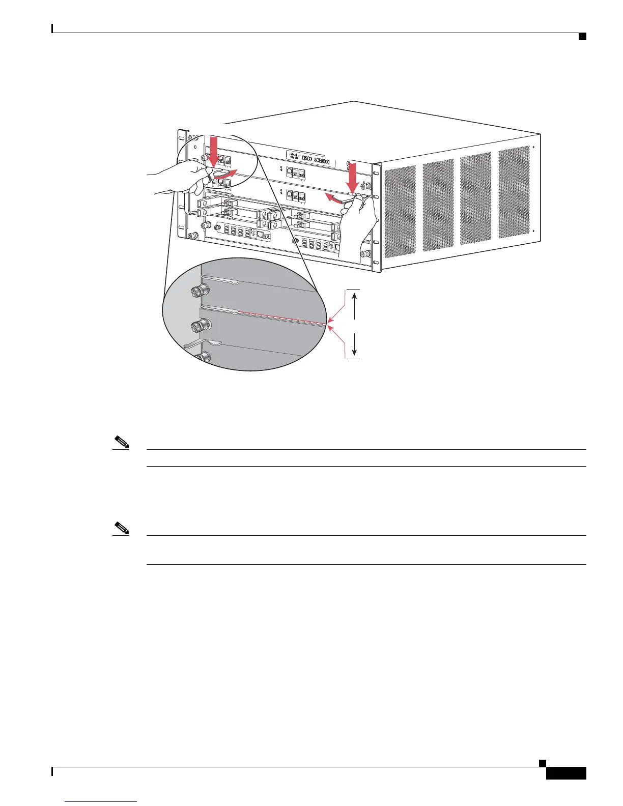
Figure 9-12 Clearing the EMI Gasket
Step 9
Using the thumb and forefinger of each hand, grasp the two ejector levers and press down to create a
small (0.040 inch [1 mm]) gap between the module EMI gasket and the module above it. (See
Figure 9-12.)
Note Do not press down too forcefully on the ejector levers. They will bend and be damaged.
Step 10 While pressing down, simultaneously close the left and right ejector levers to fully seat the module in
the backplane connector. The ejector levers are fully closed when they are flush with the module
faceplate. (See Figure 9-13)
Note Failure to fully seat the module in the backplane connector can result in incorrect operation and/or error
messages.
270908
FAN
S
T
AT
U
S
S
CM
1
S
CM
2
SIP
3
4
S
C
E
8000-FAN
SY
S
TE
M
P
O
WE
R
O
P
T
I
C
AL
B
Y
PA
S
S
S
T
ATU
S
AU
X
PO
RT 2
L
I
NK
AC
T
I
V
E
M
A
ST
ER
S
C
E
8
000
E
X
T
E
N
D
E
D
S
E
R
V
I
CE
CO
N
TRO
L
M
O
DU
L
E
OPTIC
A
L
B
Y
P
AS
S
O
PT
ICA
L
BYP
A
SS
C
O
NSOLE
1
0 10
0
1
00
0
L
IN
K
A
CT
I
V
E
PO
R
T1
A
C
A
B
C
D
B
D
S
T
A
T
U
S
C
T
RL
OP
B-
S
C
E
8
K
-
M
M
O
PT
I
C
A
L
B
YP
A
S
S1
TX
R
X
T
X
R
X
T
X
R
X
TX
R
X
A
C
A
B
C
D
B
D
S
T
AT
US
C
T
R
L
OPB-
S
CE8
K
-
M
M
O
P
T
ICA
L
B
Y
P
A
S
S
2
T
X
RX
T
X
R
X
T
X
R
X
T
X
RX
S
Y
S
TE
M
P
O
WE
R
O
P
T
I
C
AL
B
Y
PA
S
S
S
T
AT
U
S
A
U
X
P
ORT 2
1
0
1
0
0
1
0
0
0
LI
N
K
A
C
T
I
V
E
M
AS
T
ER
S
C
E
8
000
E
X
T
E
N
D
ED
S
E
RV
I
CE
CO
N
T
RO
L
M
O
DU
L
E
S
C
E
80
0
0
-
S
C
M
-
E
S
C
E
80
0
0
-
S
C
M
-
E
S
C
E
8
00
0-
S
IP
C
O
N
SOLE
10 1
00
1000
L
IN
K
A
CT
I
V
E
PO
R
T1
O
PT
ICA
L
B
Y
PA
SS
OPT
IC
A
L
BYPASS
S
T
A
T
U
S
AC
TI
VE/LINK
S
P
A
-1
X
1
0
G
E
-
L
-
V
2
S
T
AT
U
S
A
C
T
I
VE
/L
INK
S
P
A
-1
X
1
0
G
E
-
L
-
V
2
S
T
A
T
U
S
A
C
T
I
VE
/L
IN
K
S
PA
-
1
X
1
0
GE
-
L
-
V
2
S
T
A
TU
S
A
C
T
IVE/
L
I
N
K
S
PA
-
1
X
1
0
GE-
L
-
V
2
1
0
10
0
1
0
0
0
1mm
Gap between the module
EMI gasket and the
module above it.
Press down
Press down

 Loading...


