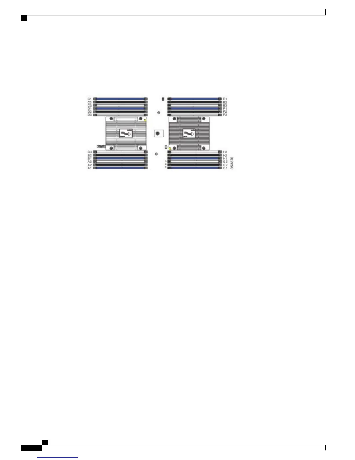
The figure below shows how DIMMs and channels are physically laid out on the blade server. The DIMM
slots in the upper and lower right are associated with the second CPU (CPU shown on right in the diagram),
while the DIMM slots in the upper and lower left are associated with the first CPU (CPU shown on left).
Figure 16: Physical Representation of DIMMs and Channels
Cisco UCS B200 M4 Blade Server Installation and Service Note
24
Servicing a Blade Server
DIMMs and Channels
 Loading...