3-2
Cisco UCS C240 Server Installation and Service Guide
OL-25761-01
Chapter 3 Maintaining the Server
Status LEDs and Buttons
Status LEDs and Buttons
This section describes the location and meaning of LEDs and buttons and includes the following topics
• Front Panel LEDs, page 3-2
• Rear Panel LEDs and Buttons, page 3-4
• Internal Diagnostic LEDs, page 3-6
Front Panel LEDs
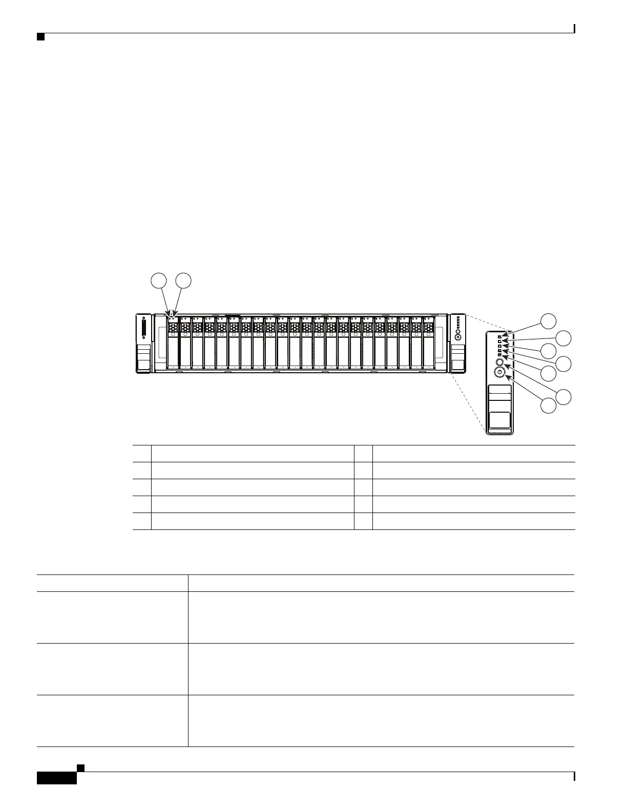
Figure 3-1 shows the front panel LEDs. Table 3-1 defines the LED states.
Figure 3-1 Front Panel LEDs
1 Hard drive fault LED 6 Fan status LED
2 Hard drive activity LED 7 System status LED
3 Network link activity LED 8 Identification button/LED
4 Power supply status LED 9 Power button/power status LED
5 Temperature status LED –
Table 3-1 Front Panel LEDs, Definitions of States
LED Name State
Hard drive fault
• Off—The hard drive is operating properly.
• Amber—This hard drive has failed.
• Amber, blinking—The device is rebuilding.
Hard drive activity
• Off—There is no hard drive in the hard drive sled (no access, no fault).
• Green—The hard drive is ready.
• Green, blinking—The hard drive is reading or writing data.
Network link activity
• Off—The Ethernet link is idle.
• Green—One or more Ethernet LOM ports are link-active, but there is no activity.
• Green, blinking—One or more Ethernet LOM ports are link-active, with activity.
HDD 1
HDD 2
HDD 3
HDD 4
HDD 5
HDD 6
HDD 7
HDD 8
HDD 9
HDD 10
HDD 11
HDD 12
HDD 13
HDD 14
HDD 15
HDD 16
HDD 17
HDD 18
HDD 19
HDD 20
HDD 21
HDD 22
HDD 23
HDD 24
3
4
5
6
7
9
8
1 2
331828