3-6
Cisco UCS C240 Server Installation and Service Guide
OL-25761-01
Chapter 3 Maintaining the Server
Status LEDs and Buttons
Internal Diagnostic LEDs
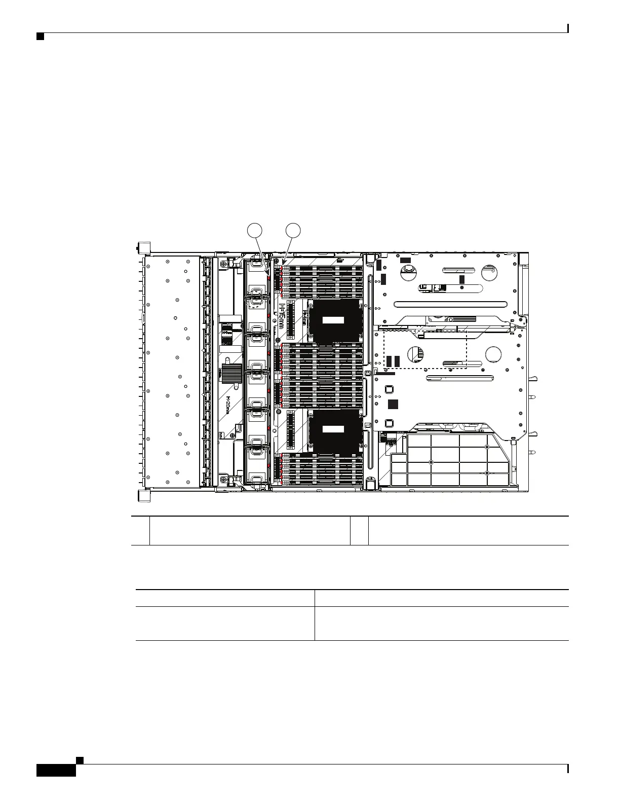
The server is equipped with a SuperCap voltage source that can activate internal component fault LEDs
up to one half-hour after AC power is removed. The server has internal fault LEDs for fan modules and
DIMMs.
To use these LEDs to identify a failed component, press the front or rear Identification button (see
Figure 3-1 or Figure 3-2) with AC power removed. An LED lights amber to indicate a failed component.
See Figure 3-3 for the locations of these internal LEDs.
Figure 3-3 Internal Diagnostic LED Locations
1 Fan module fault LEDs (one on each fan
module)
2 DIMM fault LEDs (one next to each DIMM
socket on the motherboard)
Table 3-3 Internal Diagnostic LEDs, Definition of States
LED Name State
Internal diagnostic LEDs (all)
• Off—Component is functioning normally.
• Amber—Component has failed.
SAS2
SAS1
FAN1
FAN2
FAN3
FAN4
FAN5
FAN6
CPU1
CPU2
SAS1
SAS2
Riser 1
Riser 2
SAS1
SAS2
1 2
331830