3-9
Cisco UCS C240 Server Installation and Service Guide
OL-25761-01z
Chapter 3 Maintaining the Server
Preparing for Server Component Installation
Replaceable Component Locations
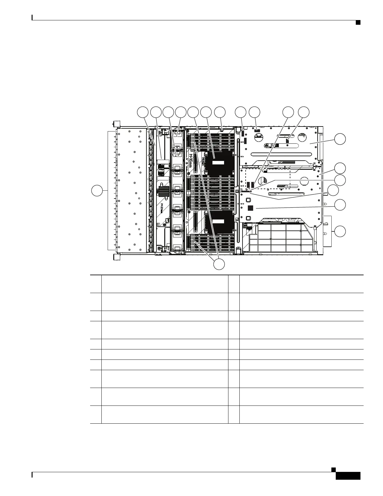
This section shows the locations of the components that are discussed in this chapter. The view in
Figure 3-5 is from the top down with the top cover and air baffles removed.
Figure 3-5 Replaceable Component Locations
The Technical Specifications Sheet for this server, which includes component part numbers, is at:
http://www.cisco.com/en/US/prod/collateral/ps10265/ps10493/C240M3_SFF_SpecSheet.pdf.
1 Drives
(hot-swappable, accessed through front panel)
11 Optional mezzanine RAID controller card,
mini-SAS connectors SAS1 and SAS2
2 Drive backplane 12 Trusted platform module socket on
motherboard
3 Drive backplane expander 13 PCIe riser 1 (three full-height slots)
4 RTC battery (on motherboard under fan tray) 14 PCIe riser 2 (one full-height slot and one
half-height slot)
5 Fan modules (six, hot-swappable) 15 SD card slot SD2
6 DIMM slots on motherboard (24) 16 SD card slot SD1
7 CPUs and heatsinks (two) 17 Internal USB 2.0 port on motherboard
8 SCU upgrade ROM header
(PBG DYNAMIC SKU)
18 Power supplies (two, hot-swappable access
through rear panel)
9 Integrated RAID mini-SAS connectors on
motherboard, SASPORT 1 and SASPORT2
19 RAID backup unit mounting locations
(two, on air baffle not shown in this view)
10 Software RAID 5 key header
(SW RAID KEY)
SAS2
SAS1
FAN1
FAN2
FAN3
FAN4
FAN5
FAN6
CPU1
CPU2
SAS1
SAS2
Riser 1
Riser 2
SAS1
SAS2
5 6
1
2 3 4 7 8 9 10 12
3213
3214
11
15
17
18
19
331833
16