3-19
Cisco UCS C240 Server Installation and Service Guide
OL-25761-01z
Chapter 3 Maintaining the Server
Installing or Replacing Server Components
Step 7 Replace the fan tray.
a. With the blue-plastic lever at each end of the fan tray in the upright and open position, set the fan
tray in place in the chassis. Use the chassis guides at each end of the fan tray to keep the fan tray
level and straight.
b. Rotate each blue-plastic lever down to the locked position. Stop when the levers click and lock.
Step 8 Replace the top cover.
Step 9 Replace the server in the rack, replace cables, and then power on the server by pressing the Power
button.
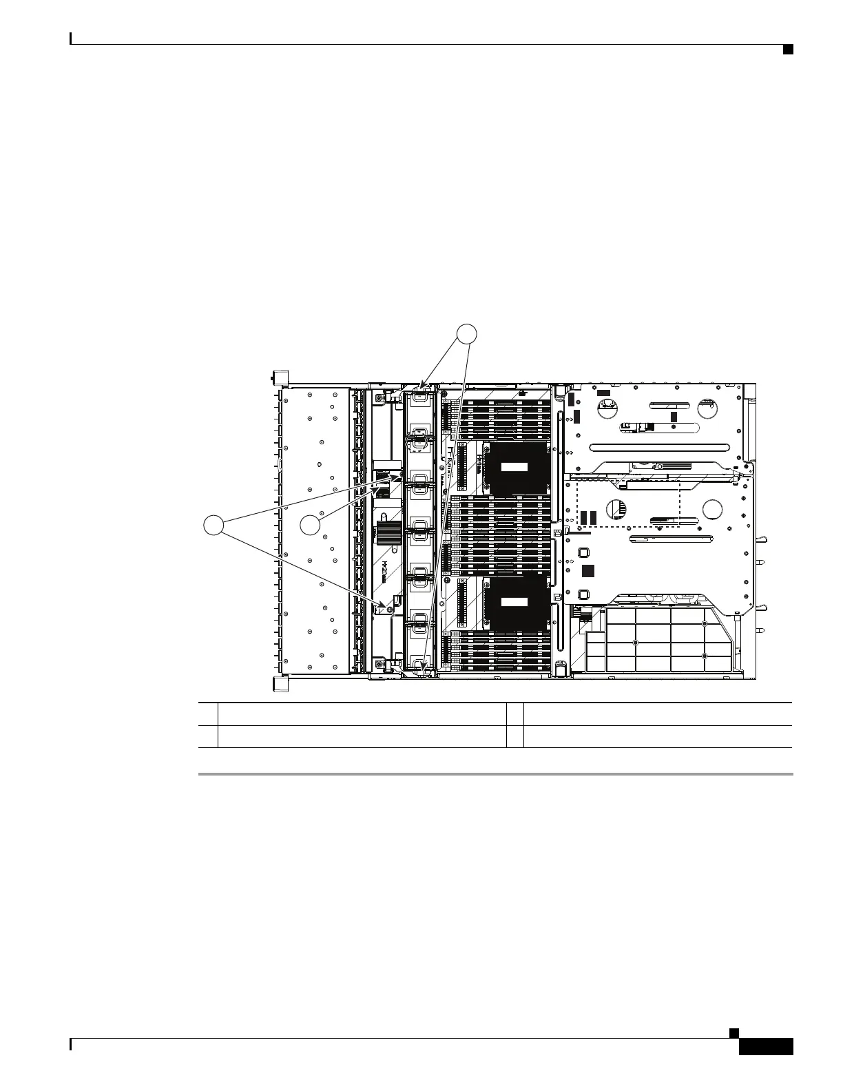
Figure 3-10 Replacing the SAS Expander
1 SAS expander securing screws (two) 3 Fan tray blue-plastic locking levers
2 SAS expander cable connectors
SAS2
SAS1
FAN1
FAN2
FAN3
FAN4
FAN5
FAN6
CPU1
CPU2
SAS1
SAS2
Riser 1
Riser 2
SAS1
SAS2
3
1 2
331838