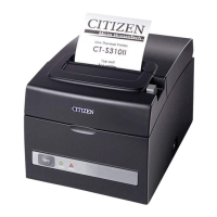
CT-S310II Series Service Manual
- 11 -
Remove “SCREW, BHT (ST), M3.0 6” that fastens “FRAME, BOTTOM-03” and “PLATE, IF-03”.
Remove two “LOCK SCREW” from the right and left of the serial connector.
Turn “PLATE, IF-03” toward you and pull it out upwardly.
Remove three “SCREW, TP (ST), M3.0 5” that fasten “SA, MAIN PCB”.
Note that one of those screws is secured with “COVER, DR CONNECTOR-03”.
<Precaution at reassembly>
When attaching “PLATE, IF-03”, align the bosses at “FRAME,
BOTTOM-03” with the holes at “PLATE, IF-03”.
Check the positions of the serial, DK and USB connectors.
Remove two “SCREW, FHT (ST), M3.0 8” that fasten “FRAME, BOTTOM-03” and the AC inlet on
“PWB (MAIN_PCB30)”. Move the AC inlet outwardly to detach it from “FRAME, BOTTOM-03”.
SCREW, BHT (ST), M3.0 6
BOSS
DK
LOCK SCREW USB
PLATE, IF-03
COVER, DR
CONNECTOR-03
SCREW, TP (ST), M3.0 5
SCREW, FHT (ST), M3.0 8
AC inlet

 Loading...