150
AXLES
SUSPENSION
STEERING
AXLE GEOMETRY
Conditions for checking and adjusting
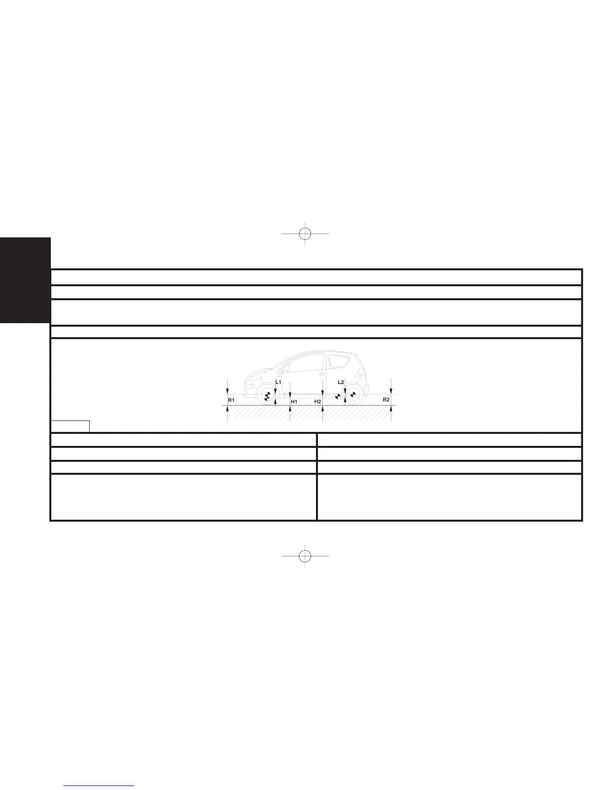
Vehicle heights at reference height
Rear heightFront height
L2L1
Tyres inflated to correct pressures. Vehicle at reference height.
Steering rack locked at mid point
(see corresponding operation).
H1 = R1 - L1
H1 = Measurement between the measuring zone underneath the front sub-
frame and the ground.
R1 = Front wheel radius under load.
L1 = Distance between the wheel axis and the measuring zone underneath
the front subframe.
H2 = R2 - L2
H2 = Measurement between the measuring zone underneath the rear sill
and the ground.
R2 =Rear wheel radius under load.
L2 = Distance between the wheel axis and the measuring zone underneath
the rear sill.
B3B200ED