FSM3 Series
Product-specic cautions
The sensor chip will degrade when used for a long
time and cause the detected ow rate to vary.
Periodically inspect the sensor chip.
Replace the working gas in the ow paths before
changing the gas type.
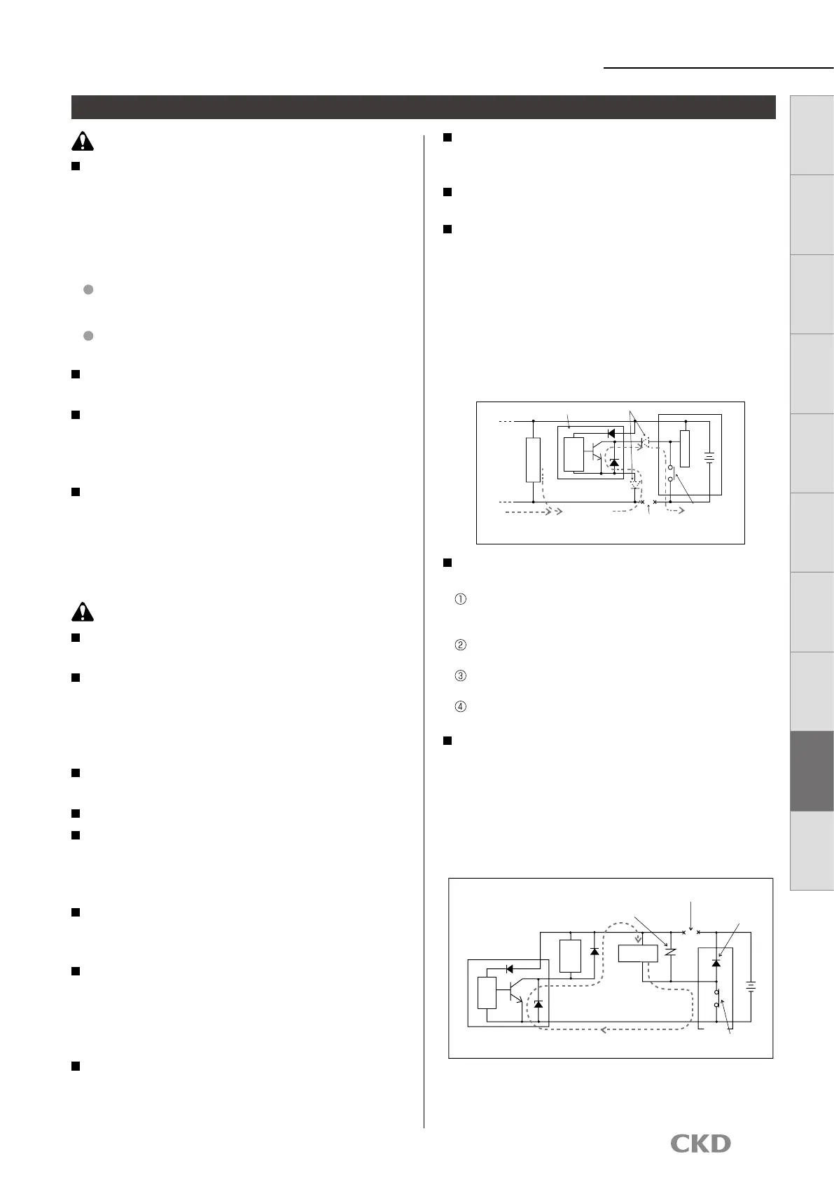
Pay attention to the reverse current caused by
disconnected wires/wiring resistance. If other
devices, including a ow rate sensor, are connected
to the same power sensor as the ow rate sensor,
and the switch output wire and power cable minus
(−) side are short-circuited to check the operation
of the control panel's input unit, or if the power
cable's minus (−) side is disconnected, reverse
current could ow to the ow rate sensor's switch
output circuit and cause damage.
Take countermeasures as followings to prevent
damages caused by reverse current.
Avoid centralizing current at the power cable, especially
the minus side power cable, and use as thick a cable as
possible.
Limit the number of devices connected to the same power
supply as the ow rate sensor.
Insert a diode parallel to the ow rate sensor's output line
to prevent the reverse current.
Insert a diode parallel to the ow rate sensor power wire's
minus (−) side to prevent the reverse current.
Care must be taken for surge current leading.
When ow rate sensor power is shared with an
inductive load that generates surges, such as a
solenoid valve or relay, if the circuit is cut off while
the inductive load is functioning, surge current
could enter the switch output circuit and cause
damage depending on where the surge absorbing
element is installed.
Working conditions for CE compliance
This product is CE-marked, indicating conformity
with the EMC Directives. EN61000-6-2; regulation
matched to immunity applies to this product.
Conditions below are necessary to comply with
these standards.
Conditions
The assessment of this product is performed by using a
cable pairing a power supply line and a signal line,
treating this cable as a signal line.
This product is not equipped with surge immunity.
Implement surge protection measures on the system side.
Do not disassemble or modify this product. Doing
so could result in faults.
Output accuracy is affected by temperature
characteristics and heat generated when energized.
Provide a standby time (5 minutes or more) after
turning the power ON for use.
Immediately after power is turned ON, this product
does not start ow rate detection switch operation
for approx. 5 seconds to complete self-diagnosis.
Provide a control circuit/program that ignores
signals for at least ve seconds after power is
turned ON.
If a problem occurs during operation, immediately
turn power off, stop use, and contact your dealer.
This product uses a micro-sensor chip, and must
be installed where it will not be subject to dropping,
impact or vibration. Handle this product as a
precision component during installation and
transportation.
Keep this product's ow rate within the rated ow
range.
Use this product within the working pressure range.
Do not turn the product's tting while the uid
pressure is on, since it may cause external leakage.
Also avoid use that may cause the tting to rotate
during operation.
If the output setting value is changed, control
system devices could operate unintentionally. Stop
devices before changing settings.
Analog output continues even if the ow rate range
is exceeded. With the display integrated, "Hi" or
"Lo" will be displayed. With display separated, the
bar display will blink.
Note that this is outside guaranteed precision.
The accuracy may vary from the initial status
depending on the working environment or working
conditions. It is recommended to check the
operation of the product periodically.
During Use & maintenance
Solenoid
valve
Relay
Main
circuit
ON
PLC
PLC output
Surge current
Flow rate sensor
Surge absorbing
element (retrotted)
Circuit cutoff with disconnection
or emergency stop
Surge absorbing
element (built-in)
Diode for reverse ow prevention
Flow rate sensor
Disconnection
Test SW
or short-circuit
Other
components
Current from
Main
circuit
Control panel
CAUTION
WARNING
PLC input
Other components
48
LCD display Bar display
IO
-
Link
Internal
structure
Separate
display
Technical
data
Operating
method
Optional
products
Safety
precautions
Related
products
 Loading...