14
Specifications
FSM3
Series
*1: The value converted to volumetric ow rate at standard condition (20°C 1 barometric pressure (101 kPa) relative humidity 65%)
*2: Use dry gas which does not contain corrosive elements such as chlorine, sulfur or acids, and which is clean and does not contain dust or
oil mist. When using compressed air, use clean air that complies with JIS B 8392-1:2012 Class 1.1.1 to 1.6.2. Compressed air from the
compressor contains drain (water, oil oxide, foreign substances, etc.) To maintain the function of this product, install a lter, air dryer (min.
pressure dew point 10°C or less), and oil mist lter (max. oil content 0.1 mg/m
3
) on the primary side (upstream side) of this product. (Refer
to the recommended values on page 42.)
*3: Compressed air is used for adjusting and inspecting this product. Accuracy for gas types other than air is a guideline.
*4: The accuracy is based on CKD's basic ow rate meter. It does not show absolute accuracy.
*5: Repeatability over a short period of time. Change over time is not included. (Refer to the product specications sheet for details.)
*6: Actual response time may differ depending on piping conditions.
*7: Current for when 24 VDC is connected, and no load is applied. The current consumption will vary depending on how the load is connected.
*8: The male side is straight and the female side is at an angle. (Refer to page 37.)
Tighten the M12 connector with a torque of 0.5 N·m or lower.
Tightening it using excessive force may lead to damages.
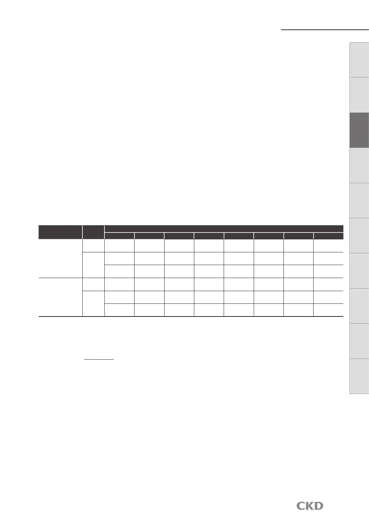
*9: Gas can be changed to argon, carbon dioxide, and argon 80% + carbon dioxide 20% with the gas change function. After changing the gas,
the ow rate measured range will be as follows. (Note that the 500 L/min and 1,000 L/min models do not have a gas change function.)
Gas
Flow
direction
Measured ow rate range (
□
/min)
005 010 020 100 200 500 101 201
Air
Nitrogen
Argon
Argon 80%+
Carbon dioxide 20%
Uni-
direction
15 to
500 mL
30 to
1000 mL
0.06 to
2.00 L
0.30 to
10.00 L
0.6 to 20.0 L 1.5 to 50.0 L
3.0 to
100.0 L
6 to 200 L
Bi-
direction
−500 to
−15 mL
−1000 to
−30 mL
−2.00 to
−0.06 L
−10.00 to
−0.30 L
−20.0 to
−0.6 L
−50.0 to
−1.5 L
−100.0 to
−3.0 L
−200 to −6 L
15 to
500 mL
30 to
1000 mL
0.06 to
2.00 L
0.30 to
10.00 L
0.6 to 20.0 L 1.5 to 50.0 L
3.0 to
100.0 L
6 to 200 L
Carbon dioxide
Uni-
direction
15 to
250 mL
30 to
500 mL
0.06 to
1.00 L
0.30 to
5.00 L
0.6 to 10.0 L 1.5 to 25.0 L 3.0 to 50.0 L 6 to 100 L
Bi-
direction
−250 to
−15 mL
−500 to
−30 mL
−1.00 to
−0.06 L
−5.00 to
−0.30 L
−10.0 to
−0.6 L
−25.0 to
−1.5 L
−50.0 to
−3.0 L
−100 to −6 L
15 to
250 mL
30 to
500 mL
0.06 to
1.00 L
0.30 to
5.00 L
0.6 to 10.0 L 1.5 to 25.0 L 3.0 to 50.0 L 6 to 100 L
The integrating ow is a reference value.
When using the integration maintaining function, be careful that the number of times maintained does not exceed the number of access
times of the storage element (the limit is 1 million times).
(Changes to the settings are not counted in number of accesses.)
Times maintained = < 1 million
Usage time
5 min
*10: This product's protection circuit is effective only for specic misconnections and load short-circuits. It does not provide protection for all
misconnections.
*11: Depending on the vibration conditions, a communication error may occur. Install this product in a place subject to as little vibration as
possible.
*12: This product measures the change in heat distribution caused by ow.
When set to horizontal direction, the convection ow can inuence a change in heat distribution, causing the zero point to shift.
*13: Piping conditions may affect accuracy. For more accurate measurements, use a straight pipe with an internal diameter ten times greater.
With the 500 L/min and 1,000 L/min models, use piping with an internal diameter of 9 mm or more. If it is less than 9 mm, accuracy may
be negatively affected.
*14: Refer to page 32 for weight.
LCD display Bar display
IO
-
Link
Internal
structure
Separate
display
Technical
data
Operating
method
Optional
products
Safety
precautions
Related
products
 Loading...