Mount an air lter upstream from suction in
compliance with use conditions to prevent the entry
of foreign matter.
Consider the atmospheric dew point and the
product's ambient temperature, and use the product
under conditions in which dew does not condense
in pipes.
When this product is used for vacuum applications
such as air suction, do not bend the tube near the
push-in tting. If stress is applied to the tube near
the push-in tting, insert an insert ring into the tube,
and connect the tube to the push-in tting.
Select the ow rate range based on the operating
vacuum pressure and suction nozzle.
Response speed may be delayed by the piping
volume between the suction nozzle and this
product. In this case, take countermeasures to
reduce piping capacity.
When the suction conrmation sensor is switched
from a pressure sensor (switch) to a ow rate
sensor (switch), sensor output (switch output) logic
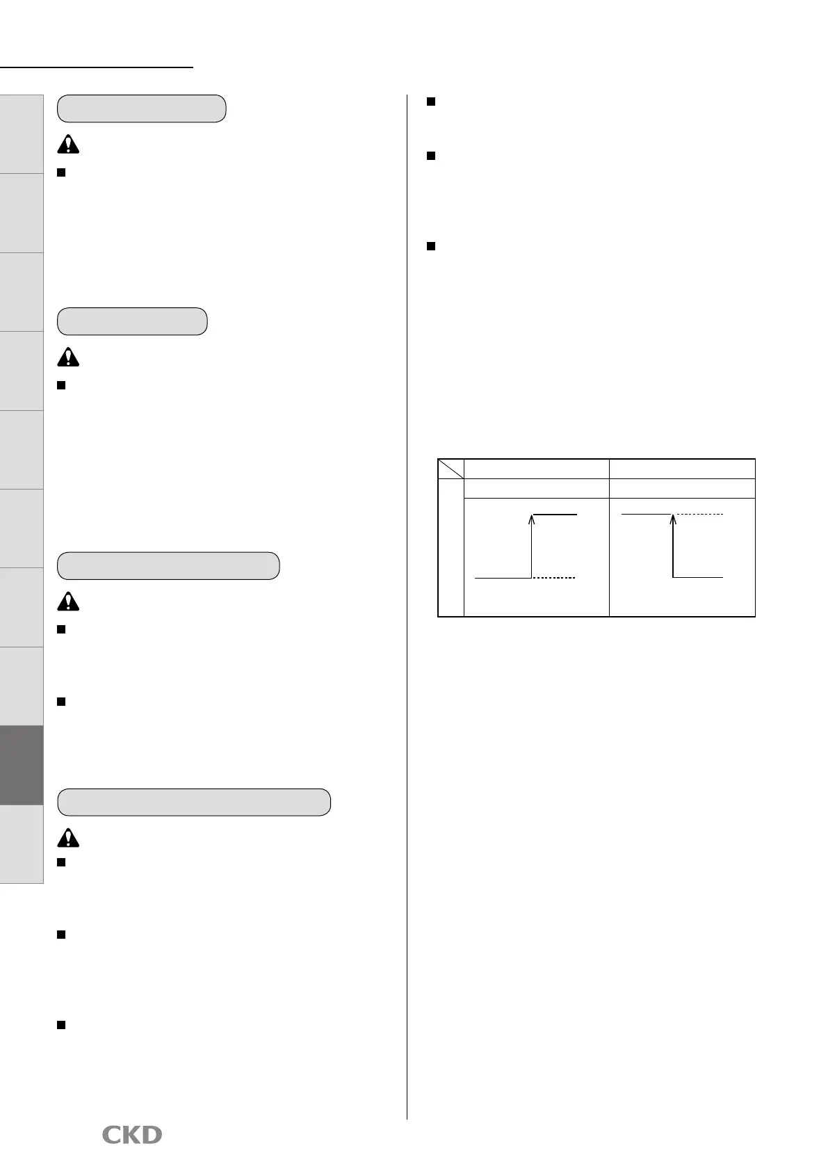
will be reversed. Refer to the drawing below.
Note that the PLC sequence program must be
changed or revised.
If source pressure or vacuum source is not supplied
when device power is turned on, "ow rate 0" =
"sensor output (switch output) ON" status is set at
the ow rate sensor (switch). Check that this is not
a problem with the PLC sequence program, etc.
Use for suction conrmation, etc.
Pressure sensor (switch) Flow rate sensor (switch)
Suction conrmation
ON at setting value or more ON at setting value or less
OFF
ON
High ow
rate side
Flow rate 0 sideHigh vacuum
side
OFF
ON
Atmospheric
pressure side
FSM3 Series
CAUTION
CAUTION
This valve cannot be used as a stop valve that
requires no leakage. Slight leakage is allowed
for in this product's specifications.
The flow path in the needle valve is not
completely free of dust generation. A final clean
filter should be used in circuits where dust
generation could be a problem.
Needle valve integrated
CAUTION
This product's flow rate is measured at a mass
flow rate unaffected by temperature or pressure.
The unit is ℓ/min, the display used when the
mass flow rate is converted to volumetric flow
rate at 20°C, 1 barometric pressure (101 kPa),
relative humidity 65%.
(For gases other than air, 20°C, 1 atmospheric
pressure (101 kPa), relative humidity 0% RH.)
Flow rate unit
CAUTION
With each series, the sensor can handle an
overflow double the measured range. If dynamic
pressure is applied near the maximum working
pressure (when a pressure difference exceeding
the max. working pressure is applied between
primary and secondary sides), the sensor may
operate abnormally. If dynamic pressure is applied,
such as when a workpiece is filled for leakage
inspection, provide a bypass circuit or restrictor so
that dynamic pressure is not applied to the sensor.
Overflow
45
LCD displayBar display
IO
-
Link
Internal
structure
Separate
display
Technical
data
Operating
method
Optional
products
Safety
precautions
Related
products
 Loading...