21
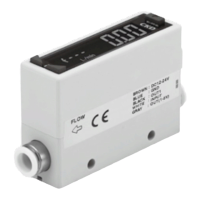
Compact ow rate sensor RAPIFLOW
FSM2 Series
Separate display
Separated display specifications
*1: The flow rate range, flow direction and gas type are automatically recognized only when the FSM2 display separated is connected. (Default state)
The FSM3 bar display, FSM-H Series, FSM-V Series, and WFK3000 Series flow rate ranges are supported, but automatic recognition is not
supported. Always set the product's flow rate range, flow direction and gas type before use.
The connectable flow rate ranges are shown in "Display for each flow rate range" below.
The "Gas Type Setting" function of this product is not a "Gas Type Switching" function that switches the sensor characteristics to match the gas type.
If a "Gas Type Switching" function is required, use the LCD display type.
When the sensor section is changed, the previous flow rate range settings, etc., will still be recorded. Always reset the settings before using.
*2: Current for when 24 VDC is connected, and no load is connected. The current consumption will vary depending on how the load is connected.
*3: This product's protection circuit is effective only for specific mis-connections and a load short-circuit. It does not provide protection against various
mis-connections.
*4: [P70] Anti-dust generation (product surface is degreased and cleaned before packing. Heat sealed into antistatic bag in clean bench (Class 1000 and
over).)
*5: When connecting to the FSM-V Series or WFK3000 Series, the cable size is different so the separate compatible sensor connection connector (e-con)
will be required. Contact your nearest CKD sales office or dealer.
The enclosed sensor connection connector (e-con) can be used with the FSM2 Series, FSM3 Series and FSM-H Series.
*6: The output impedance of the analog output section is approx. 1 kΩ. If the impedance of the connecting load is small, output and error increase. Check
error with the impedance of the connecting load before using.
Descriptions
Separate display
FSM2-D-[*1][*2]-
-[*3]
Settable flow rate range *1
mℓ 5, 10, 50, 100, 500, 1000
ℓ
2, 4, 5, 10, 12, 20, 25, 32, 50, 100,
200, 500, 1000, 1500
Operating ambient temperature/humidity 0 to 50°C
Display 4-digit + 4-digit 2-color LCD
Input voltage 1 to 5V
Output
Switch output *1
N
Output 2-points (NPN open collector output, 50 mA or less, voltage drop 2.4 V or less)
P
P Output 2-points (PNP open collector output, 50 mA or less, voltage drop 2.4 V or less)
Analog output *2
V 1 to 5 V voltage output 1-point (connecting load impedance 50 kΩ and over) *6
A 4 to 20 mA current output 1-point (connecting load impedance 0 to 300 Ω)
Power supply voltage *2
V 12 to 24 VDC (10.8 to 26.4V)
A 24 VDC (21.6 to 26.4V)
Current consumption *2 40 mA or less (when 24 VDC is connected, and no load is connected)
Lead wire φ3.7, 26 AWG or equivalent x 5-conductor (connector), insulator outer diameter φ1.0
Functions Flow rate display, flow rate display peak hold, switch output, analog output
Degree of protection IEC standards IP40-equivalent
Protection circuit *3 Power supply reverse connection protection
EMC Directive EN55011, EN61000-6-2, EN61000-4-2/3/4/6/8
Accessory
1 sensor connection connector (e-con), conforming cable AWG24 to 26, insulator outer diameter φ1.0 to 1.2
Weight (main body only) Approx. 40 g
Clean-room specifications *4 *3 P70 Anti-dust generation
Display for each flow rate range
Flow rate display
Display
range
Uni-
direction
0 to
500
mℓ/min
0 to
1000
mℓ/min
0 to
2.00
ℓ/min
0 to
4.00
ℓ/min
0 to
5.00
ℓ/min
0 to
10.00
ℓ/min
0 to
12.0
ℓ/min
0 to
20.0
ℓ/min
0 to
25.0
ℓ/min
0 to
32.0
ℓ/min
0 to
50.0
ℓ/min
0 to
100.0
ℓ/min
0 to
200
ℓ/min
0 to
500
ℓ/min
0 to
1000
ℓ/min
0 to
1.50
m
3
/min
0 to
5.00
mℓ/min
0 to
10.00
mℓ/min
0 to
50.0
mℓ/min
0 to
100.0
mℓ/min
Bi-
direction
−500
to 500
mℓ/min
−1000
to
1000
mℓ/min
−2.00
to
2.00
ℓ/min
―
−5.00
to
5.00
ℓ/min
−10.00
to
10.00
ℓ/min
―
−20.0
to
20.0
ℓ/min
― ―
−50.0
to
50.0
ℓ/min
−100.0
to
100.0
ℓ/min
−200
to
200
ℓ/min
−500
to
500
ℓ/min
−1000
to
1000
ℓ/min
−1.50
to
1.50
m
3
/min
−5.00
to
5.00
mℓ/min
−10.00
to
10.00
mℓ/min
−50.0
to 50.0
mℓ/min
−100.0
to
100.0
mℓ/min
Display resolution
1m ℓ/min 0.01 ℓ/min 0.1 ℓ/min 1 ℓ/min
0.01 m
3
/min
0.01 mℓ/min
0.1 mℓ/min
Integrating functions *2
Display range
9999999 mℓ
99999.99 ℓ 999999.9 ℓ 9999999 ℓ
99999.99 m
3
99999.99 mℓ 999999.9 mℓ
Display resolution
1 mℓ 0.01 ℓ 0.1 ℓ 1 ℓ
0.01 m
3
0.01 mℓ 0.1 mℓ
Integrated pulse output rate
5 mℓ
10 mℓ
0.02 ℓ 0.04 ℓ 0.05 ℓ
0.1 ℓ
0.12 ℓ
0.2 ℓ
0.25 ℓ 0.32 ℓ
0.5 ℓ 1 ℓ 2 ℓ 5 ℓ 10 ℓ 15 ℓ
0.05 mℓ
0.1 mℓ 0.5 mℓ
1 mℓ
* The corresponding sensor is the voltage output (1 to 5 V). If the current output or other voltage output is connected, it will not operate properly.
*1: The flow rate display is rounded off at approx. ±1% or less (forced zero).
*2: The accumulated flow is a calculated (reference) value. It is reset when the power is turned OFF.
LCD displayBar display
IO
-
Link
Internal
structure
Separate
display
Technical
data
Operating
method
Optional
products
Safety
precautions
Related
products
 Loading...