Always attach the pipes before starting wiring.
Align the uid ow direction to the direction
indicated on the pipe when connecting the pipes.
Do not install the regulator/solenoid valve, etc.,
immediately before this product. Generated drift
may cause errors. Provide a straight piping section
if required.
Before installing piping, clean out the pipes using
air blower to remove all foreign matter and cutting
chips from the pipes. The rectier or sensor chip
could be damaged if a large amount of foreign
matter, cutting chips, etc., enters.
Check that sealant tape or sealant material does not
get inside during piping.
*When using for clean room specications, make
sure that the sealant material matches the system.
The screw-in ttings of this product are compliant
with push-in ttings for pneumatic pressure. Do not
use this product for pneumatic pressure circuits
with steel pipe connections. If this product is used
for steel pipe connection, the misalignment of the
IN side steel pipe bore and OUT side steel pipe
bore will cause excessive force to be applied to the
body, as well as external leakage, risking damage
to the product.
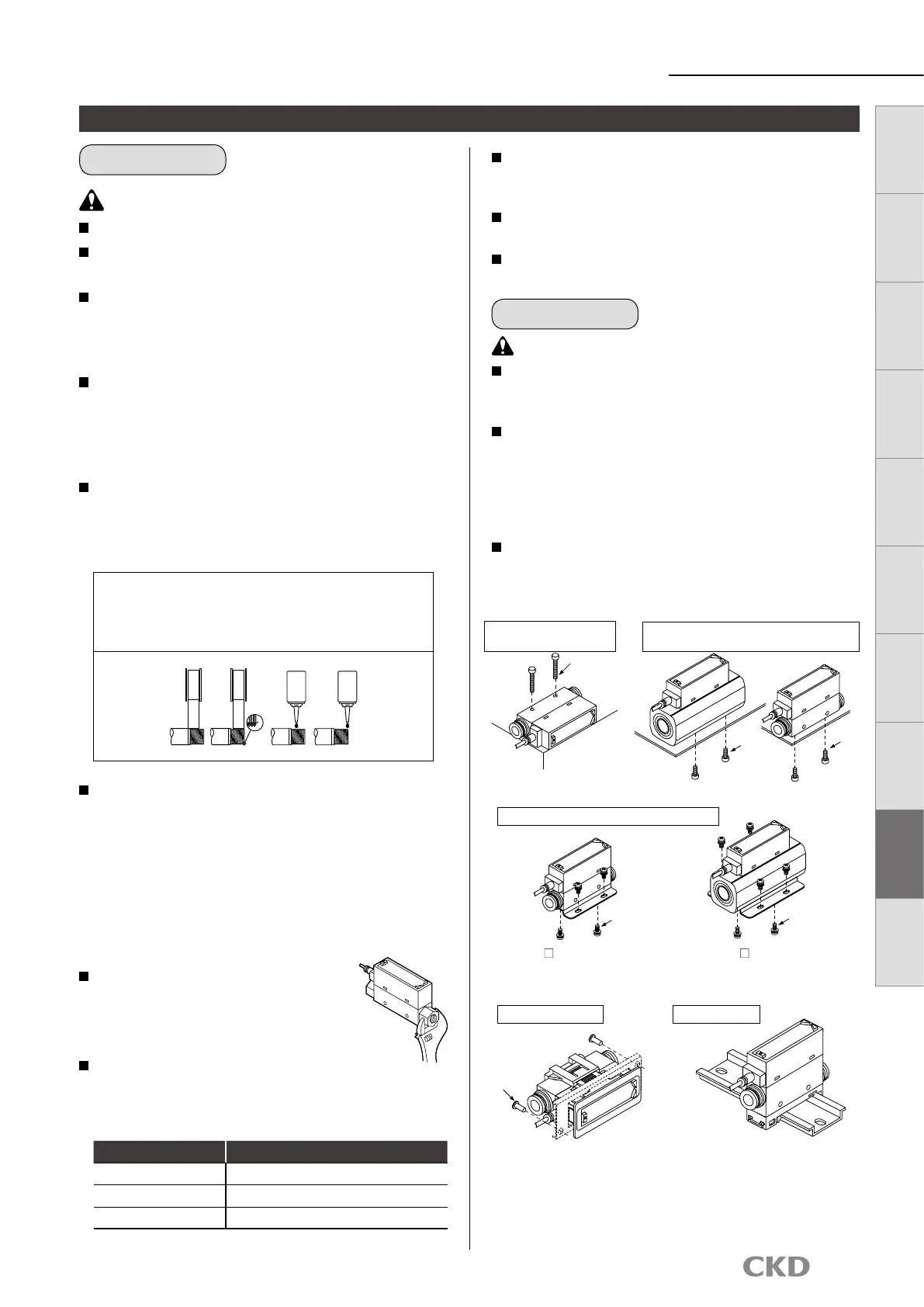
Attach a wrench to metal sections
when tightening pipes so that force is
not applied to the resin section.
Refer to the torque below so as not to
apply excessive screw-in torque or load
torque to the connection port.
When using a push-in tting, accurately insert tube
and conrm that it cannot be pulled out. Cut the tube
at a right angle with a dedicated cutter before use.
Make sure that the leakage detection solution does not
enter the product when inspecting the pipe for leaks.
Do not turn the tting while the product uid
pressure is on, since it may cause external leakage.
The LCD display type ow rate display meter uses
a liquid crystal display. This may be difcult to read
depending on the angle.
Do not install multiple product bodies in close
contact. The generation of heat on each part could
cause the product's temperature to rise, hastening
changes in characteristics or deterioration of the
resin material. When using the products in a row,
set intervals of distance of 10 mm and over.
Although the mounting is "unrestricted in vertical/
horizontal direction", the ow rate may vary
depending on difference in the mounting orientation
or piping conditions.
Mounting, installation and adjustment
Piping
Mounting
CAUTION
[
Reference value]
Port thread Tightening torque N·m
Rc1/8(G1/8) 3 to 5
Rc1/4 6 to 8
Rc1/2 16 to 18
When winding uoro resin sealing tape around threads, wind
sealing tape once or twice, leaving two to three threads open at the
end of the screw. Press tape with your ngernail tip to stick it onto
threads. When using liquid sealant, leave one to two threads open
from the end, and avoid applying too much. Check that the sealant
does not get on device threads.
(Not good)(Good)(Not good)(Good)
Sealant tape
Solid/liquid sealant
Solid/
liquid
sealant
Solid/
liquid
sealant
FSM3 Series
Product-specic cautions
CAUTION
Tighten the set screw with a tightening torque of 0.06 N·m.
Complete the piping before assembly.
If the pipes are connected after assembly, excessive stress will be
applied and may damage the product parts.
When using the panel mounting method, make sure that vibration is
not applied to the product. When using on a stainless steel body, the
vibration will be amplified and could damage the product.
Lateral mounting (use of
through hole)
Vertical mounting (use of female thread on
bottom surface)
Bracket mounting (use of dedicated bracket)
Tighten the mounting screw with a tightening
torque of 0.5 N·m.
For FSM3- 005 to 201
Single bracket model No.: FSM3-B1
Tighten the mounting screw with a tightening
torque of 0.5 N·m.
For FSM3- 501 and 102
Single bracket model No.: FSM3-B2
Mounting screws
Mounting
screws
Mounting
screws
Mounting screws
Mounting screws
Mounting screws
Panel mounting DIN rail mount
46
LCD display Bar display
IO
-
Link
Internal
structure
Separate
display
Technical
data
Operating
method
Optional
products
Safety
precautions
Related
products
 Loading...