23
FSM3
Series
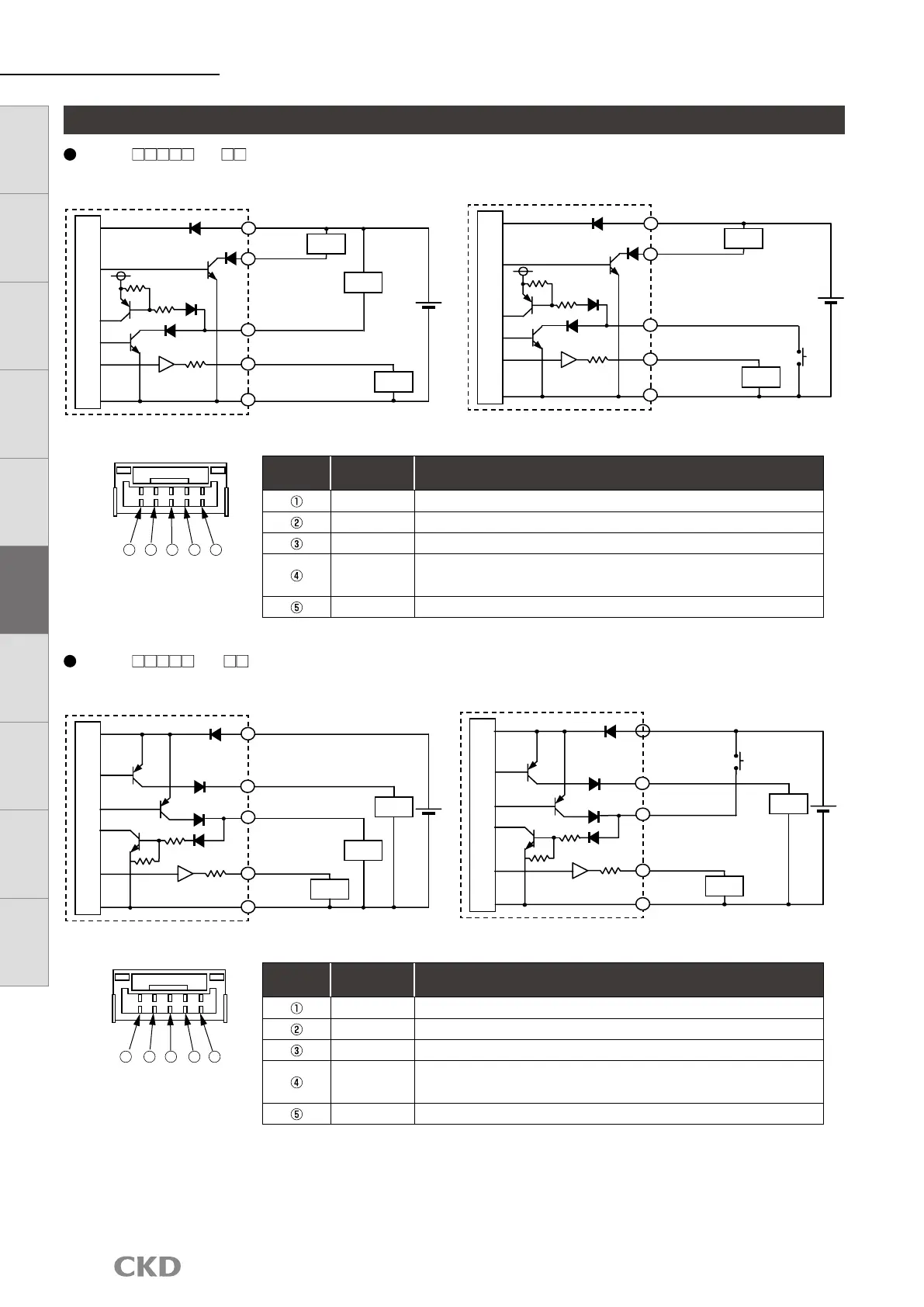
Example of internal circuit and load connection
FSM3-L B/F/ (LCD display NPN output)
Terminal
No.
Option cable
color
Name
Brown Power supply (+) (voltage output: 12 to 24 V, current output: 24 V)
Black CH1 (switch output 1: max. 50 mA)
White CH2 (switch output 2: max. 50 mA, or external input)
Gray
Analog output
Voltage output: 1 to 5 V load impedance: 50 kΩ or more
Current output: 4 to 20 mA load impedance 300 Ω or less
Blue Power supply - (GND)
FSM3-L D/H/ (LCD display PNP output)
Terminal
No.
Option cable
color
Name
Brown Power supply (+) (voltage output: 12 to 24 V, current output: 24 V)
Black CH1 (switch output 1: max. 50 mA)
White CH2 (switch output 2: max. 50 mA, or external input)
Gray
Analog output
Voltage output: 1 to 5 V load impedance: 50 kΩ or more
Current output: 4 to 20 mA load impedance 300 Ω or less
Blue Power supply - (GND)
(FSM3 side)
1 2 3 4 5
1 2 3 4 5
1
[CH2 is used as SW output] [CH2 is used as external input]
(Brown) power supply (+)
(Brown) power supply (+)
(Blue) power supply (−)
(Blue) power
supply (−)
R*
R*
Load
Load
Load
Load
Load
1
1
2
2
3
3
4
4
5
5
+
+
−
−
Main circuit
Main circuit
(Gray) Analog output
(Gray) Analog output
(Black) CH1
SW Output 1
(Black) CH1
SW Output 1
* Analog output voltage output R: approx. 1 kΩ
Current output R: approx. 100 Ω
(White) CH2
SW Output 2
(White) CH2
External input
[CH2 is used as SW output] [CH2 is used as external input]
(Brown) power supply (+)
(Brown) power supply (+)
(Blue)
Power
supply (−)
(Blue)
Power
supply (−)
R*
R*
Load
Load
Load
Load
Load
1
1
2
2
3
3
4
4
5
5
+
+
−
−
Main circuit
Main circuit
(Gray) Analog output
(Gray) Analog output
(Black) CH1
SW Output 1
(Black) CH1
SW Output 1
* Analog output voltage output R: approx. 1 kΩ
Current output R: approx. 100 Ω
(White) CH2
SW Output 2
(White) CH2
External input
(FSM3 side)
LCD displayBar display
IO-Link
Internal
structure
Separate
display
Technical
data
Operating
method
Optional
products
Safety
precautions
Related
products
 Loading...