15
[Example of model No.]
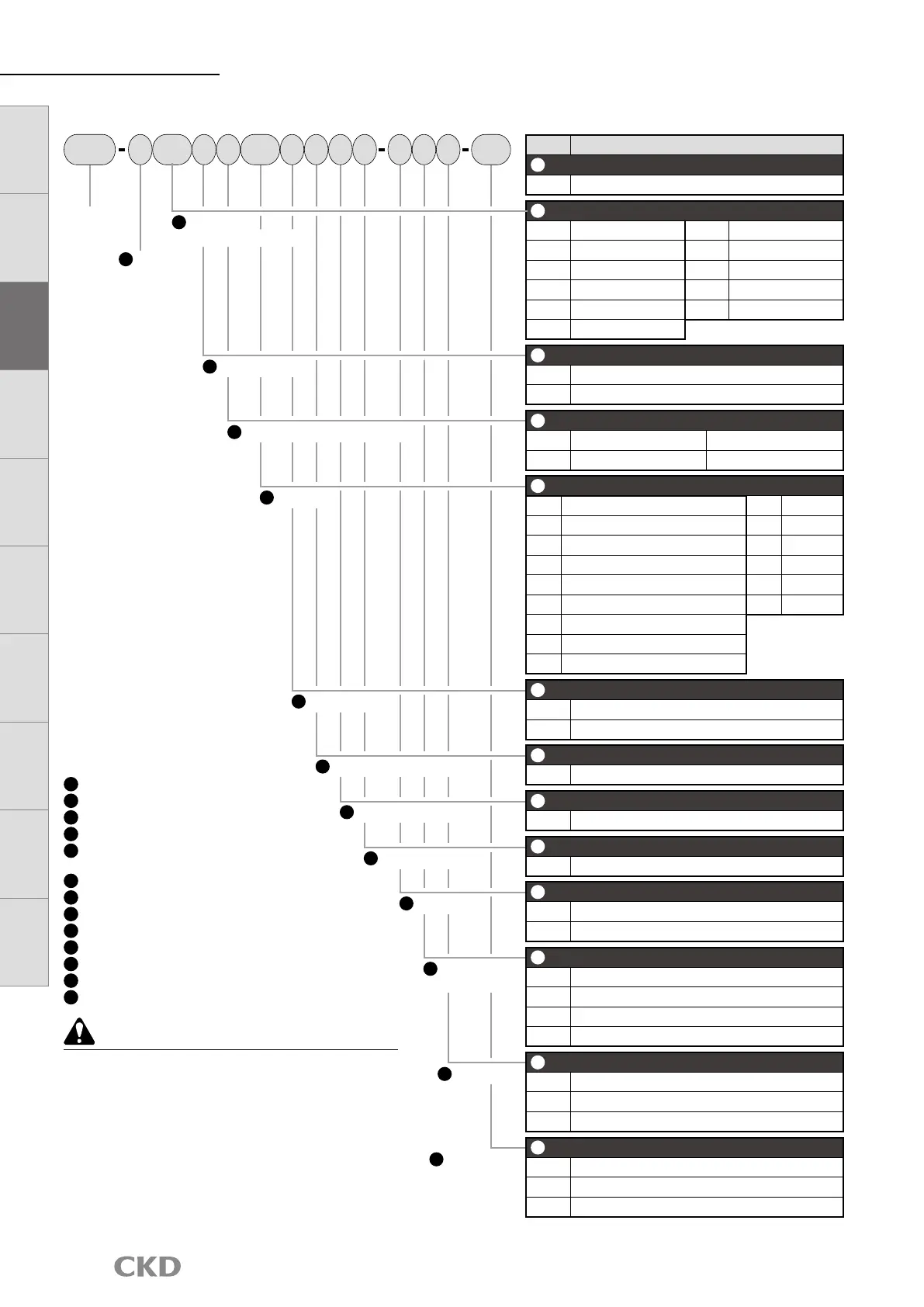
FSM3-C005U1BH1L1N-GHR-P70
Model: RAPIFLOW FSM3 Series
A
Display C : IO-Link
B
Flow rate range
005
: 500 mL/min
C
Flow direction U : Uni-direction
D
Body material/compatible fluids
1 : Resin/air
E
Port size BH : Push-in
(φ4 mm for tube)
F
Piping direction 1 : Straight
G
Output specifications
L : IO-Link
H
Unit specifications 1 : SI units only
I
Valve option N : None
J
Cable G :
M12 both ends connector cable (3 m)
K
Mounting attachments
H : Bracket
L
Attachments R : Company certification
M
Clean-room specifications
P70
: Anti-dust generation
C
Flow direction
D
Body material/compatible uids
A
Display
Model No.
E
Port size
H
Unit specications
L
Attachments
F
Piping direction
G
Output specications
J
Cable
M
Clean-room
Specications
I
Valve option
K
Mounting
attachments
FSM3
005
BH
P70
UC 1 1 L N1 G H R
FSM3
Series
How to order
Precautions for model No. selection
*1: During selection, always check the compatibility table on the
next page.
*2: Check using the connection shape and dimensions (page 17)
of the G screw when selecting.
*3: Note that if you mount the elbow fitting in a downward
position, it will interfere with the DIN rail mounting.
*4: Note that the bracket mounting position may interfere with the
elbow fitting.
*5: Optional parts will come with the product. They are not pre-
assembled.
*6:
Product surface is degreased before packaging and heat sealed
into an antistatic bag on the clean bench (Class 1000 and over).
*7: The wetted section is degreased in addition to the
specifications on P70.
Code Content
A
Display
C IO-Link
B
Flow rate range (full scale ow rate)
005 500 mL/min 500 50 L/min
010 1 L/min 101 100 L/min
020 2 L/min 201 200 L/min
050 5 L/min 501 500 L/min
100 10 L/min
102 1000 L/min
200 20 L/min
C
Flow direction
U Uni-direction
B Bi-direction
D
Body material/compatible uids
Body material Compatible uids
1 Resin
Air (Gas can be changed)
E
Port size
BH Push-in (for φ4 mm tube)
AB G1/8 *2
CH Push-in (for φ6 mm tube) BB G1/4 *2
DH Push-in (for φ8 mm tube)
CB G1/2 *2
EH Push-in (for φ10 mm tube)
AC NPT1/8
HH Push-in (for φ1/4" tube) BC NPT1/4 *2
JH Push-in (for φ3/8" tube)
CC NPT1/2
AA Rc1/8
BA Rc1/4
CA Rc1/2
F
Piping direction
1 Straight
2 Elbow *3
G
Output specications
L IO-Link communication
H
Unit specications
1 SI units only
I
Valve option
N None
J
Cable
Blank None
G M12 both ends connector cable (3 m)
K
Mounting attachments *4, *5
Blank None
H Bracket 1 (for models 200 L or less)
J Bracket 2 (for models 500 or 1000 L)
M DIN rail mounting (for models 200 L or less)
L
Attachments
Blank None
R Company certication
S Company certication + traceability certicate
M
Clean-room specications
Blank None
P70 Anti-dust generation *6
P80 Oil prohibited *7
B
Flow rate range
(full scale ow rate)
LCD displayBar display
IO
-
Link
Internal
structure
Separate
display
Technical
data
Operating
method
Optional
products
Safety
precautions
Related
products
 Loading...