WS1CI & WS1.25CI Manual Page 33
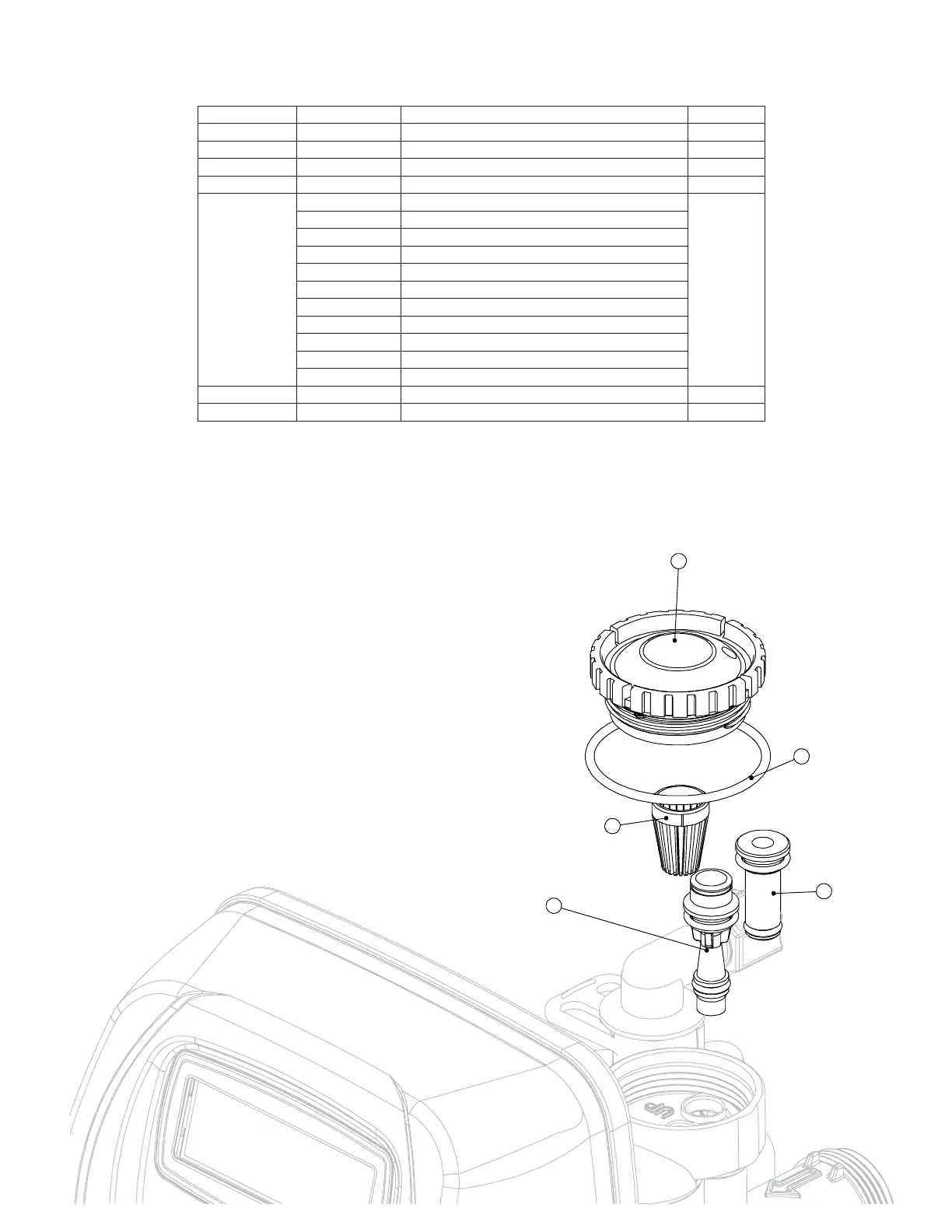
Injector Cap, Injector Screen, Injector, Plug and O-Ring
1
2
3
4
5
Note: For upfl ow position, injector is located in the up hole and injector plug is in the other hole. WS1CI
upfl ow bodies are identifi ed by having the DN marking removed. For a backwash only fi lter, injector plugs
are located in both holes.
*The injector plug and the injector each contain one 011 (lower) and 013 (upper) o-ring.
Drawing No. Order No. Description Quantity
1 V3176 Injector Cap 1
2 V3152 O-ring 135 1
3 V3177 Injector Screen 1
4 V3010-1Z WS1 Injector ASY Z Plug 1
5
V3010-1A WS1 INJECTOR ASY A BLACK
1
V3010-1B WS1 INJECTOR ASY B BROWN
V3010-1C WS1 INJECTOR ASY C VIOLET
V3010-1D WS1 INJECTOR ASY D RED
V3010-1E WS1 INJECTOR ASY E WHITE
V3010-1F WS1 INJECTOR ASY F BLUE
V3010-1G WS1 INJECTOR ASY G YELLOW
V3010-1H WS1 INJECTOR ASY H GREEN
V3010-1I WS1 INJECTOR ASY I ORANGE
V3010-1J WS1 INJECTOR ASY J LIGHT BLUE
V3010-1K WS1 INJECTOR ASY K LIGHT GREEN
Not Shown V3170 O-ring 011 *
Not Shown V3171 O-ring 013 *
 Loading...