WS1CI & WS1.25CI Manual Page 11
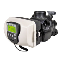
Water Meter or Meter Plug
The water meter is installed on the outlet side of the control valve. The water meter uses a turbine to measure the volume of treated
water. The turbine rotates with the fl ow of water and reports its rate of rotation through Hall effect
5
circuitry to the printed circuit
(PC) board. This rotation permits the PC board to record the total volume of treated water and the fl ow rate. The small centrally
located magnet is shielded from water, which substantially reduces iron-fouling problems with the turbine.
The turbine is accurate to within
± 5% over a wide operating fl ow rate range (0.95 lpm (0.25 gpm) up to control valve maximums)
and has a very low pressure drop. Water used for regeneration is not metered. If the control valve is set to prefi ll the regenerant,
water used between the prefi ll cycle up to the start of the regeneration cycle is metered. If the control valve is in regeneration mode
(e.g. a backwash cycle) and there is a water demand, that water usage is not metered.
When facing the front of the control valve, the water meter is positioned on the left-hand side of the control valve. Allow suffi cient
clearance to clean and repair the water meter without disconnecting the plumbing or disassembling any other parts of the control
valve.
Control valves can be ordered with a meter plug (i.e. no electronics or turbine) rather than a water meter if desired. Control valves
without meters should only be set up for time clock operation (i.e. no water meter, no demand-initiated regeneration). Control valves
with water meters provide a wider variety of useful information (see OEM General Instructions for list of information).
A unique feature of this control valve is the ability to display actual water usage for the last 63 days. The values are initially stored
as “----”. This means the value is unknown. As days pass values are stored as “0” for no fl ow or the actual volume. The counting of
the volume starts at the regeneration time. If no regeneration time can be set (i.e. when the valve is set for immediate regeneration)
the counting of volume starts at 00:00. Day 1 is yesterday, day 2 the day before yesterday, etc. As new values are added the oldest
history disappears.
Another unique feature is that the valve automatically calculates a reserve capacity when set up as a softener with “Volume
Capacity” set to “AUTO” and the “Regeneration Time Option” set to “Normal” or “Normal + on 0”. The actual reserve capacity is
compared to the volume capacity remaining immediately prior to the preset regeneration time. A regeneration will occur if the actual
reserve capacity is less than the volume capacity remaining. The actual reserve capacity is calculated by using the estimated reserve
capacity and adjusting it up or down for actual usage.
The estimated reserve capacity for a given day of the week is the maximum value stored for the last three non-trivial water usages
(i.e. more than 0.08 M
3
(20 gallons) per day) in seven-day intervals.
Mixing Valve
The mixing valve is installed on the outlet side of the control valve. The mixing valve is used to blend raw water with treated water.
To adjust the blended water, close the mixing valve. Open a water faucet to the desired fl ow rate. Open the mixing valve until the
desired hardness is reached. Close the faucet.
Installation Fitting Assemblies
The installation fi ttings are used to connect the optional bypass or the control valve to the plumbing system. There are eight
installation fi tting assemblies available:
1. 1” NPT PVC elbow fi tting assembly
2. ¾” & 1” PVC solvent weld elbow fi tting assembly
3. 1” straight brass sweat fi tting assembly
4. ¾” straight brass sweat fi tting assembly
5. 1” plastic male NPT fi tting assembly
6. 1 1/4” plastic male NPT fi tting assembly
7. 1” plastic male BSPT fi tting assembly
8. 1 1/4” plastic male BSPT fi tting assembly
5
Some semiconductor materials exhibit a phenomenon in the presence of a magnetic fi eld that is adaptable to sensing devices.
When a current is passed through one pair of wires attached to a semiconductor, another pair of wires properly attached and oriented
with respect to the semiconductor will develop a voltage proportional to the magnetic fi eld present and the current in the other pair
of wires. Holding the exciting current constant and moving a permanent magnet near the semiconductor produces a voltage output
proportional to the movement of the magnet. Hall effect devices provide a high speed response, excellent temperature stability, and
no physical contact.
 Loading...