Page 10 WS1CI & WS1.25CI Manual
The refi ll fl ow control assembly is installed in an easy to access refi ll elbow located on top of the control valve. The refi ll fl ow
control assembly is attached to the control valve with a locking clip. The locking clip allows the elbow to rotate 270 degrees so the
outlet can be orientated toward the regenerant tank.
The control valve has a standard refi ll elbow to which a 3/8” fl exible tube can be connected. An optional elbow can be ordered
which accommodates a ½” fl exible tube for a high regenerant draw rate situation (G injectors and larger). Both elbows use the same
refi ll fl ow control and retainer.
If the control valve is to be used as a non-regenerant fi lter control valve, the refi ll elbow is removed and replaced with a refi ll port
plug P/N V3195-01.
Drain Line Flow Control and Fitting Assembly
The drain line fl ow control assembly includes a drain line fl ow control and a fi tting. The drain line fl ow control allows proper media
bed expansion by regulating the fl ow rate to the drain. The drain line fl ow control is a fl exible washer-like part with an orifi ce and a
precision molded contour. The fl ow rates are within ± 10% over the pressure range of 1.4 bar (20 psi) to 8.6 bar (125 psi). See Table
7 for fl ow rate information.
The drain line fl ow control and fi tting are located on top of the control valve and replaceable without the use of special tools.
The drain line fl ow control can be installed in the standard ¾” drain line elbow, which accommodates 5/8” polytube or ¾” NPT
drain line connections. The optional nut and polytube insert for the ¾” drain line elbow is designed for use with fl exible polytube
only. The ¾” drain line elbow can be rotated 180 degrees so the outlet can be orientated to the nearest drain. The same retainer is
used for all drain line fl ow controls for the ¾”. Drain line fl ow controls designed for the ¾” fi tting are available for fl ow rates rang-
ing from 2.6 to 37.9 lpm (0.7 to 10 gpm).
An optional 1” straight drain line fi tting is available to accommodate drain line fl ow rates ranging from 34.1 to 94.6 lpm (9 to 25
gpm). This fi tting is straight but still connects to the control valve using the same locking clip. The drain line fl ow control is located
between two fi tted parts (i.e. the fi tting acts as the retainer). The nut is unscrewed to access the drain line fl ow control.
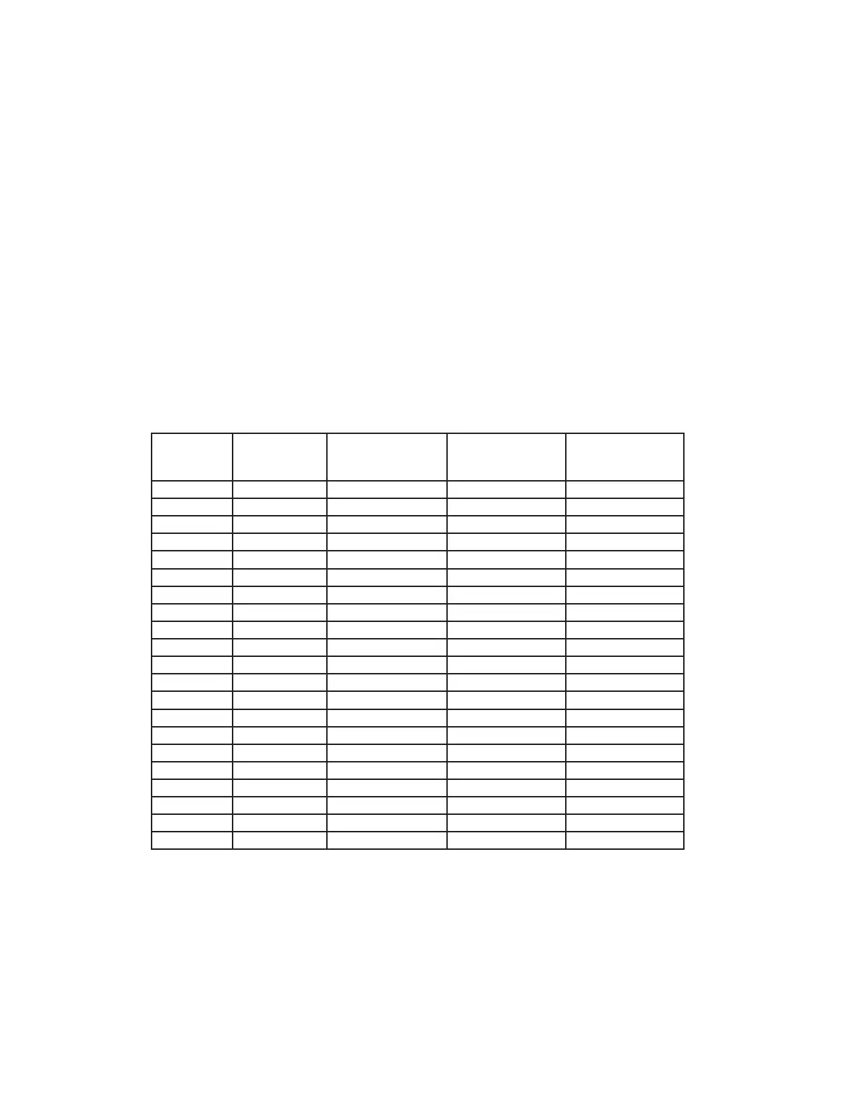
Table 7
Drain Line Flow Control and Fitting Assembly Information
Drain Line
Fitting
Drain Line Flow
Control Order
No.
Number on Drain
Line Flow Control
Backwash Flow Rate
(gpm)
Backwash Flow Rate
(lpm)
¾” V3162-007 007 0.7 2.6
¾” V3162-010 010 1.0 3.8
¾” V3162-013 013 1.3 4.9
¾” V3162-017 017 1.7 6.4
¾” V3162-022 022 2.2 8.3
¾” V3162-027 027 2.7 10.2
¾” V3162-032 032 3.2 12.1
¾” V3162-042 042 4.2 15.9
¾” V3162-053 053 5.3 20.1
¾” V3162-065 065 6.5 24.6
¾” V3162-075 075 7.5 28.4
¾” V3162-090 090 9.0 34.1
¾” V3162-100 100 10.0 37.9
1” V3190-090 090 9.0 34.1
1” V3190-100 100 10.0 37.9
1” V3190-110 110 11 41.6
1” V3190-130 130 13 49.2
1” V3190-150 150 15 56.8
1” V3190-170 170 17 64.4
1” V3190-200 200 20 75.7
1” V3190-250 250 25 94.6
 Loading...