Page 46 WS1CI & WS1.25CI Manual
Replace the motor if necessary. Do not lubricate the motor or the gears. To reinstall the motor, move the spring clip loop to the
right and hold. Gently turn the motor while inserting so that the gear on the motor meshes with the gears under the drive gear cover.
Release the spring clip loop and continue to rotate the motor until the wires are horizontal and the motor housing engages the small
plastic bulge inside the drive bracket motor retainer. Reconnect the motor plug to the two-pronged jack on the lower left-hand side
of the PC board. If the motor will not easily engage with the drive gear when reinstalling, lift and slightly rotate the motor before
reinserting. Reconnect the power plug.
Replace the valve cover. After completing any valve maintenance, press and hold NEXT and REGEN buttons for 3 seconds or
unplug power source jack (black wire) and plug back in. This resets the electronics and establishes the service piston position. The
display should fl ash all wording, then fl ash the software version (e.g. 308) and then reset the valve to the service position.
Drive Cap Assembly, Main Piston and Regenerant Piston
The drive assembly must be removed to access the drive cap assembly. The drive cap assembly must be removed to access the
piston(s). The drive cap assembly is threaded into the control valve body and seals with an o-ring. To remove the drive cap
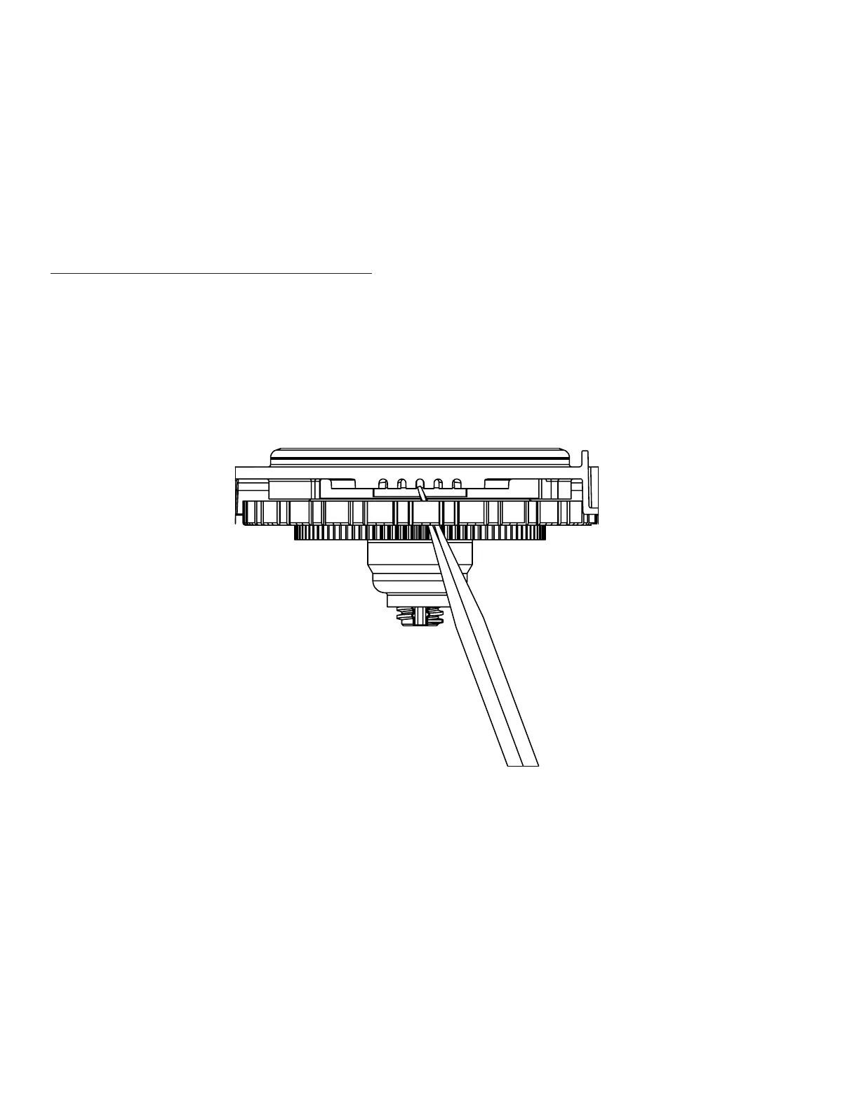
assembly use the special plastic wrench or insert a ¼” to ½” fl at blade screwdriver into one of the slots around the top 2” of the drive
cap as sem bly so it engages the notches molded into the drive back plate around the top 2” of the piston cavity. See Figure 5. The
notches are visible through the holes. Lever the screwdriver so the drive cap assembly turns counter clockwise. Once loosened,
unscrew the drive cap assembly by hand and pull straight out.
The drive cap assembly contains the drive cap, the main drive gear, drive cap spline, piston rod and various other parts that should
not be dissembled in the fi eld. The only replaceable part on the drive cap assembly is the o-ring. Attached to the drive cap assembly
is the main piston (downfl ow or upfl ow) and if a regenerant is used, a regenerant piston.
Figure 5
 Loading...