NX700/NX700E
- 22 -
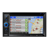
1-7. Installation of Rear cover (2)
No. PARTS CODE
Q'T
1. Push the roller of processed rear cover * Confirm that operates smoothly
3 times. without caught.
(Right and left two portions for each)
2. Confirm FPC(J102, J104, J105)
and 2P lead.
3. Stick heat rubber on the upper side A 345-6395-00 1
of IC103 of processed Escutcheon.
4. Attach processed rear cover on
processed Escutcheon,
fix it with screw(B). B 780-2604-50 4
WORKING DIAGRAM WORKING PROCESS WORKING POINT
(A)
A
B
B
processed
Escutcheon
processed
rear cover
2P lead
FPC
(J102)
FPC
J104
FPC
J105
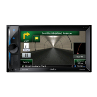
2. Processing of Main unit
2-1. Processing of DVD mechanism
No. PARTS CODE
Q'T
1. Put lower chassis A 331-4807-00 1
on the Main PWB holder. B 312-0505-01 1
2. Put the insulator on lower chassis. (Fig.1) C 347-8504-00 1
3. Attach DVD mechanism D 929-2170-80 1
on processed lower chassis.
4. Attach upper chassis E 312-0506-00 1 * Fit at 4 dowels.
on processed DVD mechanism,
and fix it with machine screw(F). F 714-2604-8B 5 * Follow screw sequence. (1 to 5)
5. Put the spacer on upper side G 347-8760-00 1
of upper chassis.
6. Turned the front side of
processed DVD mechanism below,
and fix it with machine screw(H). H 714-2604-8B 2
7. Turned the upper side of
processed DVD mechanism below,
and fix it with machine screw(I). I 714-2604-8B 2
8. Unlock Flex-socket of DVD mechanism.
9. Turned the rear side of
processed DVD mechanism below.
10. Attach front plate, J 309-1911-00 1 * Fit at 2 dowels.
and fix it with machine screw(K). K 714-2604-8B 3 * Follow screw sequence. (6 to 8)
11. Unlock Flex-socket of DVD mechanism.
WORKING DIAGRAM WORKING PROCESS WORKING POINT
A
B
C
D
E
F
F
dowel
(3)
G
H
I
J
K
K
Unlock
Flex-socket of
DVD mechanism
(2)
(1)
(4)
(5)
dowel
dowel
dowel
dowel
(7)
(6)
(8)
basic line
basic line
(Fig.1)
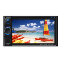
1-8. Installation of Escutcheon (1)
No. PARTS CODE
Q'T
1. Fix the upper side of
processed Escutcheon with screw(A). A 780-2003-03 3
2. Fix the lower side of
processed Escutcheon with screw(B). B 780-2003-03 2
WORKING DIAGRAM WORKING PROCESS WORKING POINT
A B
processed
Escutcheon
 Loading...