6
20B Main Electrical System:
Note:
All voltage measurements should be in reference to the (B-) connection on the Pad
Solenoid.
1. Is there a minimum of 36.0Vdc across the input terminals of the “Main Solenoid” and the
“IDrive Key Relay” with the “Key Switch” turned “ON”?
NO, is the battery charger plugged into the wall outlet? When the Charger is plugged into the
wall outlet the Charger Internal Inhibit Switch will “Open” and turn everything “OFF”. Is the
5Amp Fuse in series with the Key Switch good, otherwise check the Key Switch and wiring?
YES, Go to Step2.
2. With the “Key Switch” turned “ON”. Is there a minimum of 36.0Vdc across the Load
terminals of the Pad Solenoid with the Pad Switch Buttons not depressed?
NO, check the Main Solenoid, Pad Motor, Pad Motor C.B. and wiring.
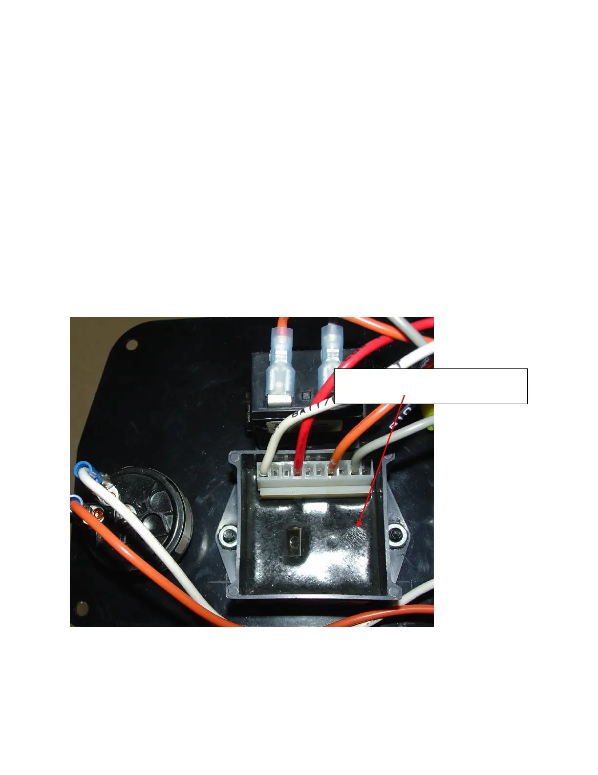
41035A Battery/Low Voltage/Delay Module:
Note:
All voltage measurements should be in reference to Pin 10 of the 41035A Battery/Low
Voltage/Delay Module:
41035A Battery/Low Voltage/Delay
Module

 Loading...