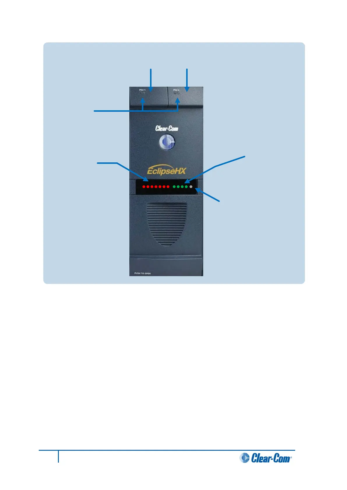
Figure 24: Power supplies: Front panel lights and controls
The front panel alarm lights, power supply lights, and reset button are shown in Figure 24.
An alarm source triggers the red main alarm light and also one of the additional six red
alarm lights, allowing the system operator to identify or correct alarm conditions before they
affect the operation of the matrix.
Each of the four green power supply lights stays on continuously to show that the power
supplies are receiving sufficient AC current. When one of these lights switches off, the power
supplies must be replaced or repaired.
Under normal operating conditions, the red front-panel alarm lights stay off, while the
green power supply lights stay on continuously.
Note:
The XP type power supplies (part 740101Z) may need to be adjusted if E-QUE, E-FIB,
IVC-32 or LMC-64 interface cards are installed. For more information, see the
Eclipse HX Upgrade Guide.
Power-One power supply units (part 720379Z) should not be adjusted.
Euro Cassette
Power Supply 1
Euro Cassette
Power Supply 2
Euro Cassette
Alarm lights
Alarm reset
button
Power supply lights
(
green when lit):
+
12 V light
+
5
V light
+
3.
3 V light
-12
V light
Alarm lights
(red
when lit):
Main alarm light
External alarm light
Temp alarm light
Fan
-fail alarm light
PSU1
fail light
PSU2
fail light
Fan-on alarm light
66
Eclipse HX-Median User Guide