1-16 750-166
CB780/CB784
ASSEMBLY
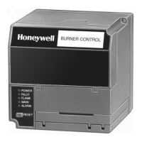
Fig. 12—Purge Card installation.
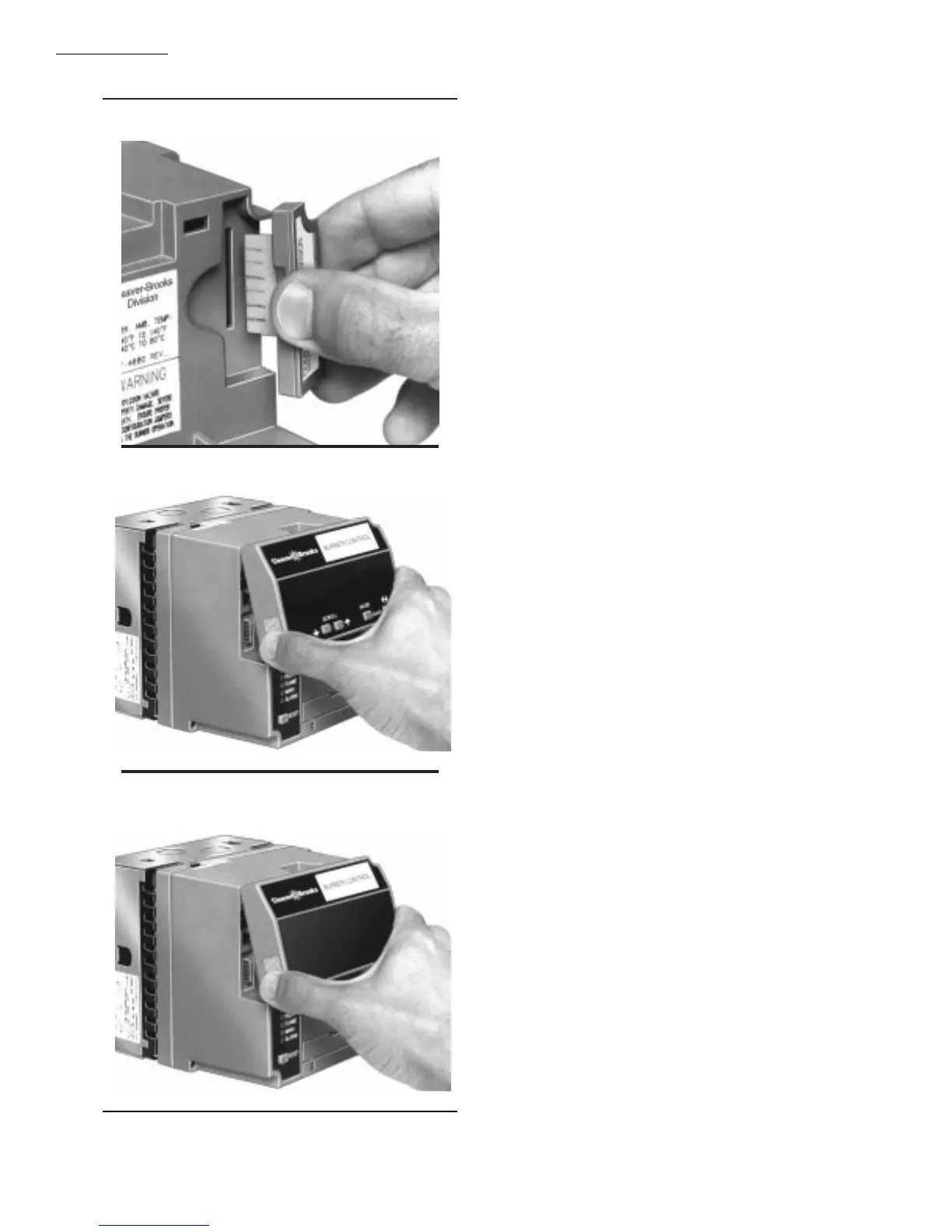
Fig. 13—Keyboard Display Module mounting.
Fig. 14—Control Bus mounting.
REMOTE MOUNTING OF KEYBOARD DISPLAY
MODULE (VFD)
1. The Keyboard Display Module (VFD) can be mounted
either on the face of a panel door or on other remote locations;
see Fig. 15.
2. When mounting the Keyboard Display Module on the
face of a door panel, closely follow these instructions:
a. Select the location on the door panel for flush mount-
ing. Pay attention to the insertion dimension of the two
Keyboard Display Module screws, two interlocking
ears and the two plug-in connectors to allow for
sufficient clearance, 1/4 inch minimum inward from
the surface of the door panel.
b. Use the Keyboard Display Module as a template; see
Fig. 28. Mark the two screw locations, two interlock-
ing ear locations and two plug-in connector locations.
Drill the pilot holes for the mounting screws. Provide
for two holes on the door panel for the interlocking
ears and plug-in connector holes.
c. Mount the Keyboard Display Module securing the
two no. 4 screws.
INSTALLING PLUG-IN FLAME SIGNAL
AMPLIFIER
1. Disconnect power supply before beginning installation
to prevent electrical shock and equipment damage. More than
one disconnect may be involved.
2. Align the amplifier circuit board edge connector with
the keyed receptacle on the CB780/CB784. Verify the am-
plifier nameplate faces away from the Relay Module, see
Fig. 16.
3. Push in the amplifier until the circuit board is fully
inserted into the receptacle and then push the amplifier
toward the CB780/CB784 retaining clasp.
4. Verify the amplifier is firmly in place.
5. Perform all required checkout tests.
INSTALLING THE FLAME DETECTOR
NOTE: Table 2 lists the flame detection systems available
for use with the CB780/CB784. Make sure the correct
combination of amplifier and flame detector(s) is used.
Proper flame detector installation is the basis of a safe and
reliable flame safeguard installation. Refer to the instruc-
tions packed with the flame detector and the equipment
manufacturer instructions; see Fig. 17.
Keep the flame signal leadwires as short as possible from
the flame detector to the wiring subbase. Capacitance in-
creases with leadwire length, reducing the signal strength.
The maximum permissible leadwire length depends on the
type of flame detector, leadwire and conduit. The ultimate
limiting factor in the flame detector leadwire is the flame
signal; see Table 9.