750-166 1-31
amplifier and energize the FLAME LED. Clean the flame
detector(s) to make sure that it will detect the smallest
acceptable pilot flame. If using Auto-Check or Self-Check-
ing Amplifier and 1M ohm/volt meter, the flame signal will
fluctuate every time the amplifier does a self-check or a
shutter check.
NOTE: Low fuel pressure limits, if used, could be open. If
so, bypass them with jumpers during this test.
1. Open the master switch.
2. Close the manual main fuel shutoff valve(s).
3. Connect a manometer (or pressure gauge) to measure
pilot gas pressure during the turndown test.
4. Open the manual pilot shutoff valve(s).
5. Close the master switch and start the system with a
call for heat. Raise the set point of the operating control-
ler. The program sequence should start, and PREPURGE
should begin.
6. When the PILOT IGN begins, set the Run/Test Switch
to TEST position to stop the sequence. The FLAME LED
will come on when the pilot ignites.
NOTE: If the sequence does not stop, reset the system and
make sure you set the Run/Test Switch to TEST within
the first eight seconds of the PILOT IGN sequence.
IMPORTANT: You have eight seconds or three seconds,
depending on PFEP selected, to position the Run/Test
Switch to the TEST position to stop the sequence after
the start of the PILOT IGN period.
7. Turn the pilot pressure down very slowly, reading the
manometer (or pressure gauge) as it drops. Stop instantly
when the FLAME LED goes out. Note the pressure at the
CB780/CB784 flame relay dropout point. The pilot is at the
minimum turndown position. Immediately turn up the pilot
pressure until the FLAME LED comes on again or the flame
signal increases to 1.25 Vdc.
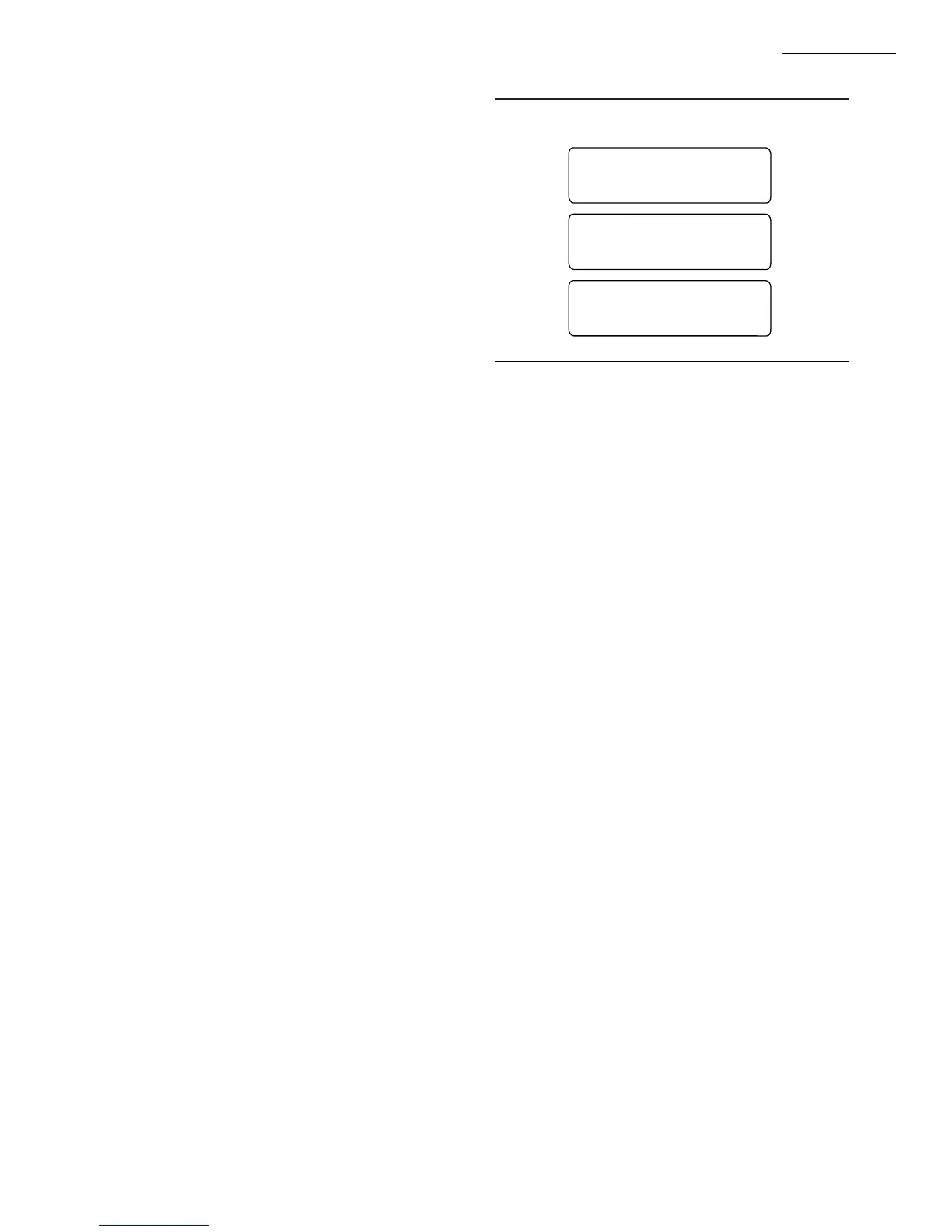
NOTE: If there is no flame for fifteen seconds with the
sequence stopped at this point, the CB780/CB784 will
lockout and flash a lockout message; see Fig. 27.
8. Repeat step 7 to verify the pilot gas pressure reading at
the exact point the FLAME LED light goes out.
9. Increase the pilot pressure immediately until the
FLAME LED comes on, and then turn it down slowly to
obtain a pressure reading just above the dropout point or until
the flame signal increases to 1.25 Vdc.
CB780/CB784
CHECKOUT
M5001
LOCKOUT #16 PFEP
* Flame-out Timer*
Condition at the
time of lockout . . .
PILOT HOLD:
(Run/Test Sw)
10. Set the Run/Test Switch in the RUN position and let
the sequence proceed. At ten seconds into the Ignition Trial
period, make sure the automatic main fuel valve(s) open;
then smoothly open the manual main fuel shutoff valve(s) (or
any other manually opened safety shutoff valve(s), if used)
and watch for main burner ignition. If the main burner flame
is established, proceed to step 18.
NOTE: This step requires two people, one to open the
manual valve(s) and one to watch for ignition.
11. If the main burner flame is not established within ten
seconds, close the manual main fuel shutoff valve(s) and
open the master switch. If the lightoff was rough, the pilot
flame size is too small.
12. Recycle the burner and stop the sequence in the PI-
LOT IGN period by using the Run/Test Switch.
13. Increase the pilot flame size by increasing its fuel flow
until a smooth main flame is accomplished.
14. Reposition the flame scanner sight tube or use orifices
until the pilot flame signal voltage is in the range of 1.25 to
1.50 Vdc.
15. When the main burner lights reliably with the pilot at
turndown, disconnect the manometer (or pressure gauge)
and turn the pilot gas flow up to that recommended by the
equipment manufacturer.
16. If used, remove the bypass jumpers from the sub-
base terminals, limits/controls, or switches.
17. Run the system through another cycle to check for
normal operation.
18. Return the system to normal operation.
Fig. 27—Flame-out timer lockout.