1-28 750-166
CB780/CB784
CHECKOUT
• Flame signal with hot combustion chamber—all
installations.
• Safety shutdown tests—all installations.
See Figs. 1 and 2 for location of component parts and
Fig. 7 or wiring subbase specifications for terminal locations.
PRELIMINARY INSPECTION
Perform the following inspections to avoid common
problems. Make certain that:
1. Wiring connections are correct and all terminal screws
are tight.
2. Flame detector(s) is clean, and installed and positioned
properly. Consult the applicable instructions.
3. Correct combination of amplifier and flame detec-
tor(s) is used. See Table 2 in the Specifications section.
4. Plug-in amplifier and purge card are securely in place.
5. Burner is completely installed and ready to fire; con-
sult equipment manufacturer instructions. Fuel lines are
purged of air.
6. Combustion chamber and flues are clear of fuel and
fuel vapor.
7. Power is connected to the system disconnect switch,
(master switch).
8. Lockout is reset (push in reset button) only if the Relay
Module is powered; see Figs. 1 and 2.
9. Run/Test Switch is in RUN position.
10. System is in the STANDBY condition. STANDBY
message is viewable in the VFD.
11. All limits and interlocks are reset.
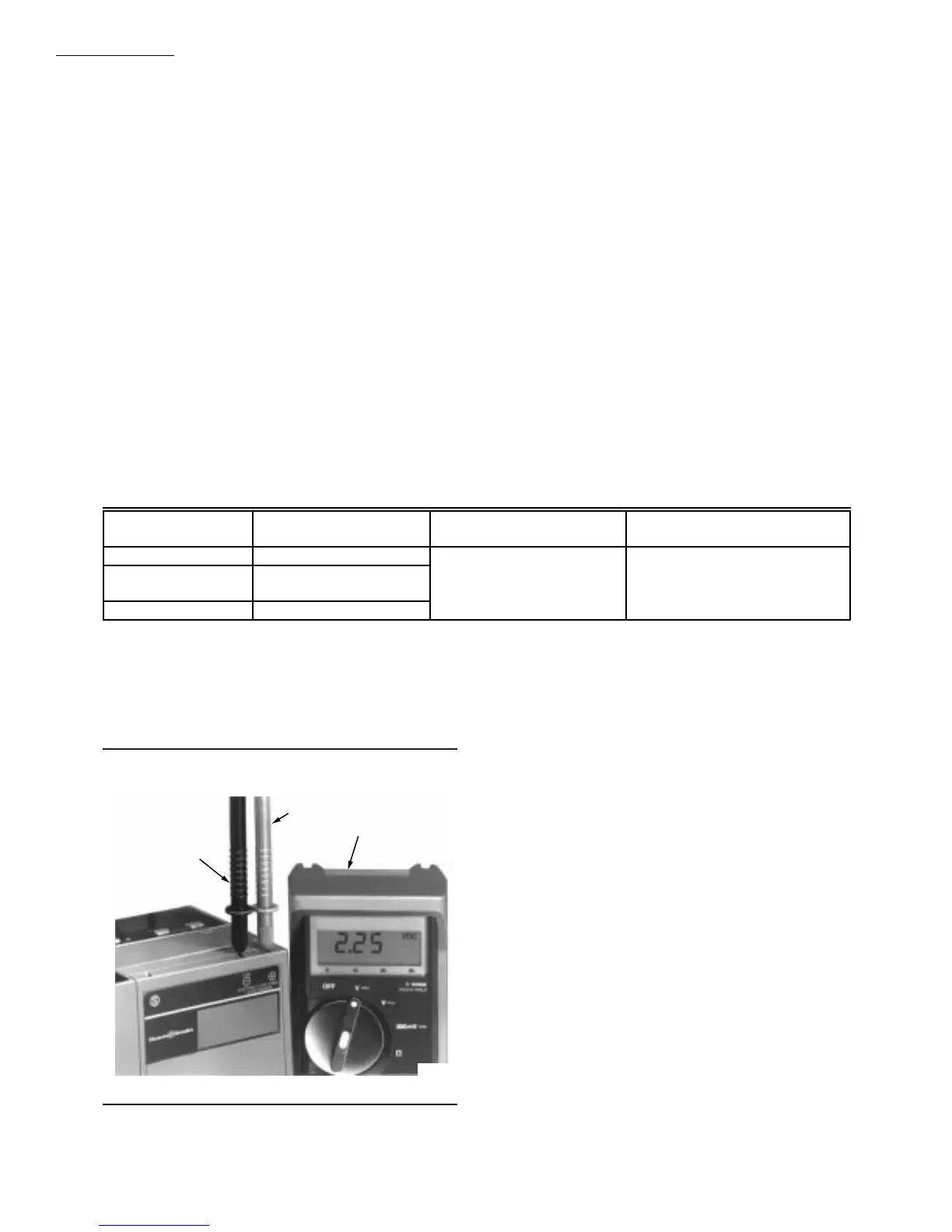
FLAME SIGNAL MEASUREMENT
(TABLE 9 AND FIG. 26)
Measure the flame signal at the appropriate times as
defined in the following Checkout tests. Read the flame
signal in volts dc at the flame amplifier test jacks + and
(Com) or at the Keyboard Display Module.
1. Use 1M ohm/volt meter with a 0 to 10 Vdc capability.
2. Set the 1M ohm/volt meter to the 0 to 10 Vdc range.
3. Insert the positive (red) probe into the + jack of the
flame amplifier. Insert the negative (black) probe into the
(Com) jack of the flame amplifier; see Fig. 26.
4. Allow a few seconds for the meter reading to stabilize.
TABLE 9—FLAME SIGNAL.
5. If using Auto-Check or shutter check amplifiers, read
the average stable voltage, disregarding the peaks and val-
leys caused by the self-checking operation.
6. The meter reading must be as specified in Table 8 after
all tests are completed and all adjustments made.
As an option, the flame signal can be checked by using the
Keyboard Display Module.
If the signal is unstable or less than the minimum accept-
able voltage, check flame detector installation and circuitry.
1. Check the supply voltages at terminals 4 (L1) and L2
(N). Make sure the master switch is closed, connections are
correct, and the power supply is of the correct voltage, fre-
quency and is sinusoidal.
2. Check the detector wiring for defects including:
• Incorrect connections.
• Wrong type of wire.
• Deteriorated wire.
• Open circuits.
• Short circuits.
• Leakage paths caused by moisture, soot or accu-
mulated dirt.
NEGATIVE (-)
METER LEAD
POSITIVE (+)
METER LEAD
ONE
MEGOHM/VOLT
METER
M7383
Flame
Detector
Flame Signal
Amplifier
Minimum Acceptable
Steady dc Voltage
a
Maximum Expected
dc Voltage
817-1121 833-2741
b
1.25 Vdc 5.0 Vdc at Keyboard
817-1742 833-2722 or
833-2723
c
Display Module
or
817-1743 833-2724 5.0 Vdc at 1M ohm/volt meter
a
This minimum or stronger signal should easily be obtained if the detector is correctly installed and positioned to properly sense
the flame. This voltaged must be obtained before completing checkout.
b
The flame signal amplifier circuitry istested one-half second every five seconds during burner operation and shuts down the
burner if the amplifier fails (all installations).
c
This flame amplifier is Auto-Check
type.
Fig. 26—Flame signal measurement.