750-166 1-25
TABLE 7—SITE CONFIGURABLE
JUMPER OPTIONS.
CB780/CB784
OPERATION • STATIC CHECKOUT
Jumper
Number Description Intact Clipped
JR1 Pilot Flame
Establishing
Period (PFEP)
10 Seconds 4 Seconds
JR3 Start-up
Interlock Check
Disabled Enabled
NOTE: For all standard installations, these jumpers
should be left intact, unless otherwise indicated on
wiring diagram.
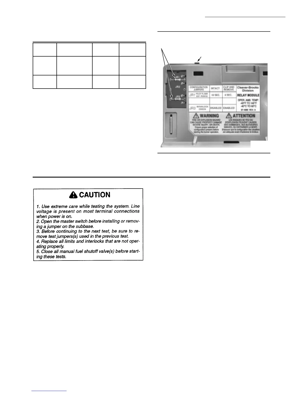
Fig. 24—Selectable site-configurable jumpers.
RUN/TEST SWITCH
SELECTABLE CONFIGURATION JUMPERS
M7397
Static Checkout
EQUIPMENT RECOMMENDED
1. Voltmeter (20 kohm/volt minimum sensitivity) set on
the 0-300 Vac scale.
2. Two jumper wires; no. 14 wire, insulated, 12 inches
[304.8 mm] long with insulated alligator clips at both ends.
GENERAL INSTRUCTIONS
1. Perform all applicable tests listed in Static Checkout,
Table 8, in the order listed.
2. Make sure all manual fuel shutoff valve(s) are closed.
3. Raise the setpoint of the operating controller to simu-
late a call for heat.
4. For each test, open the master switch and install the
jumper wire(s) between the subbase wiring terminals listed
in the Test Jumpers column.
5. Close the master switch before observing operation.
6. Read the voltage between the subbase wiring termi-
nals listed in the Voltmeter column.
7. If there is no voltage or the operation is abnormal,
check the circuits and external devices as described in the
last column.
8. Check all wiring for correct connections, tight termi-
nal screws, correct wire, and proper wiring techniques. Re-
place all damaged or incorrectly sized wires.
9. Replace faulty controllers, limits, interlocks, actuators,
valves, transformers, motors and other devices as required.
10. Ensure normal operation is obtained for each required
test before continuing the checkout.
11. After completing each test, be sure to remove the
test jumper(s).
CAUTION
1. Use extreme care while testing the system. Line
voltage is present on most terminal connections
when power is on.
2. Open the master switch before installing or
removing a jumper on the subbase.
3. Before continuing to the next test, be sure to
remove test jumper(s) used in the previous test.
4. Replace all limits and interlocks that are not
operating properly. Do not bypass limits and
interlocks.
5. Close all manual fuel shutoff valve(s) before
starting these tests.
After checking all wiring, perform this checkout before
installing the CB780/CB784 on the subbase. These tests
verify the Wiring Subbase is wired correctly, and the exter-
nal controllers, limits, interlocks, actuators, valves, trans-
formers, motors and other devices are operating properly.
NOTE: Do not perform a dielectric test with theCB780/CB784
installed. Internal surge protectors will break down and
conduct a current. This could cause the CB780/CB784 to
fail the dielectric test or possibly destroy the internal
lightning and high current protection.