750-166 1-15
CB780/CB784
ASSEMBLY
IMPORTANT: The CB780 will not function properly with-
out one of the following mounted correctly: Keyboard
Display Module, or Control Bus .
MOUNTING KEYBOARD DISPLAY MODULE
(VFD)
1. Align the two interlocking ears of the Keyboard Dis-
play Module with the two mating slots on the CB780/CB784;
see Fig. 13.
2. Insert the two interlocking ears into the two mating slots
and with a hinge action push on the lower corners of the
Keyboard Display Module to secure it to the CB780/CB784.
3. Verify the Keyboard Display Module is firmly in place.
MOUNTING CONTROL BUS
1. Align the two interlocking ears with the two mating
slots on the CB780/CB784; see Fig. 14.
2. Insert the two interlocking ears into the two mating
slots and push on the lower corners of the Control Bus to
secure it to the CB780/CB784.
3. Be sure the Control Bus is firmly in place.
Assembly
MOUNTING CB780/CB784
NOTE: For installation dimensions, see Fig. 1.
RELAY MODULE MOUNTING
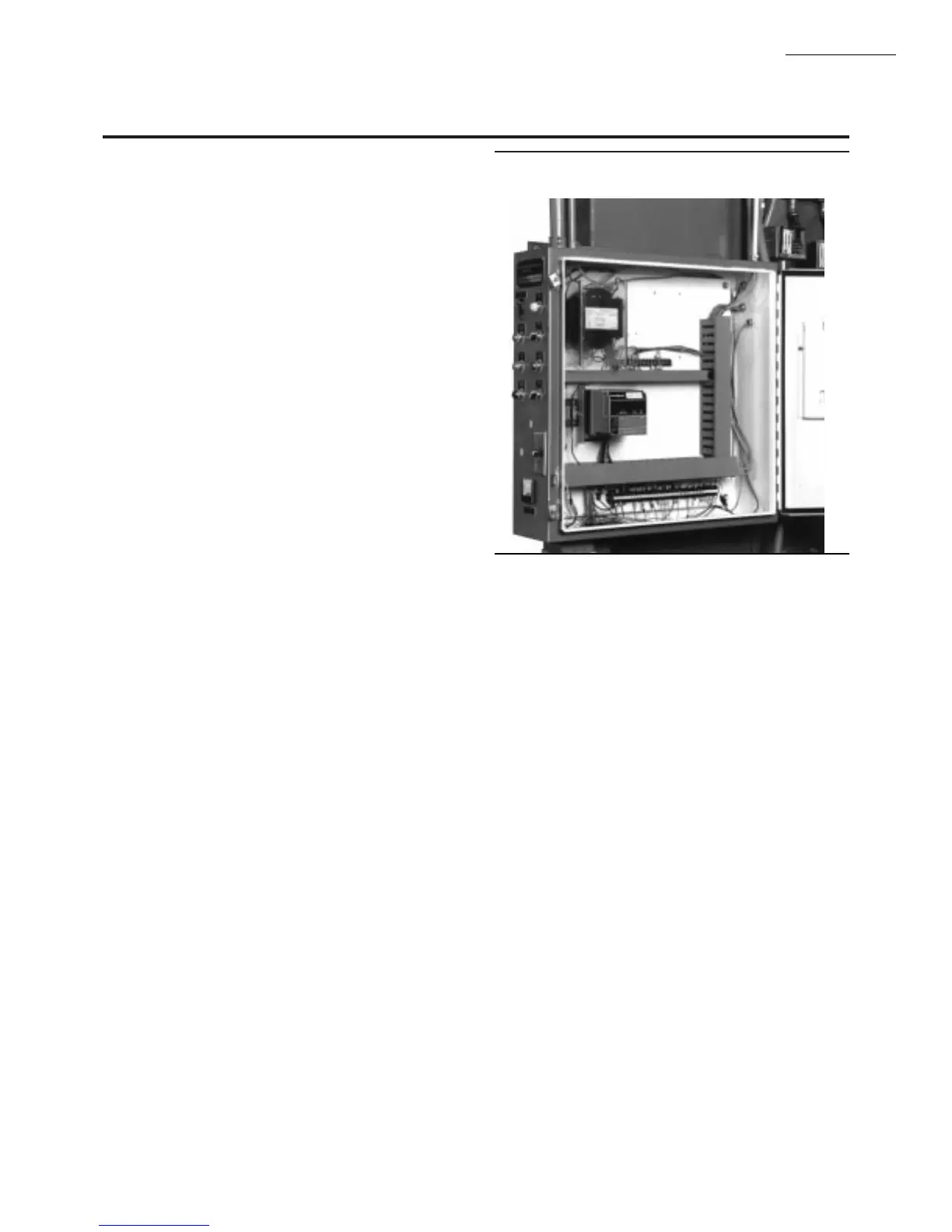
1. Mount the CB780/CB784 vertically, see Fig. 11, or
mount horizontally with the knife blade terminals pointing
downward. The CB780/CB784 must be in an electrical
enclosure.
2. Select the location in the electrical enclosure. Be sure
to allow adequate clearance for servicing, installation and
removal of the CB780/CB784, Keyboard Display Module,
flame amplifier, flame amplifier signal voltage probes, elec-
trical signal voltage probes, and electrical connections.
a. Allow an additional two inches below the CB780/CB784
for the flame amplifier mounting.
d. Allow an optional three-inch minimum to both sides
of the CB780/CB784 for electrical signal voltage
probes.
3. Make sure no subbase wiring is projecting beyond the
terminal blocks. Tuck wiring in against the back of the sub-
base so it does not interfere with the knife blade terminals or
bifurcated contacts.
IMPORTANT: The CB780/CB784 must be installed with a
plug-in motion rather than a hinge action.
4. Mount the CB780/CB784 by aligning the four L shaped
corner guides and knife blade terminals with the bifurcated
contacts on the wiring subbase and tightening the two screws
securely without deforming the plastic.
INSTALLING THE PURGE CARD
1. Remove the Keyboard Display Module or Control
Bus, see Fig. 13 or 14.
2. Remove the current Purge Card from the CB780/CB784
by pulling the plastic support cover upward .
3. Make sure that the Purge Card selected has the desired
timing.
4. Insert Purge Card into the opening of the CB780/CB784
compartment, see Fig. 12.
5. Reinstall the Keyboard Display Module or Control
Bus onto the CB780/CB784 and restore power to the
device.
6. Run the burner system through at least one complete
cycle to verify the system is operating as desired.
Fig. 11—Electrical panel installation.